
Fluke T150 Manual
PDF manual · 4 Pages
English



Quick check
Incorrect answer, please try again.
Chat with your Fluke T150 manual using AI
Get instant AI answers from your Fluke T150 manual
Ask anything about the Fluke T150. Answers come from this manual, with the pages they are based on.
T150 Maintenance Schedule
Fluke recommends a calibration interval of 1 year.
Touch probe tips together, verify battery and indicators, then measure a known voltage. Do not use the tester if it fails.
Examine the case for cracks or missing plastic. Do not use the product if it is damaged.
Free maintenance reminders
Timed to your purchase date. Always free, unsubscribe anytime.
Ask a Question
Do you recommend T150?
Yes NoVideo Manual
Fluke Spannungs- und Durchgangsprüfer T150/VDE Vorstellung + Funktionserläuterung
Frequently Asked Questions
The T150 detects voltages from low levels upward: LEDs operate from 12 V to 690 V AC/DC; the LCD displays from 6 V to 690 V with 1 V resolution on models with an LCD.
Is this answer helpful?
Yes. By pressing both load buttons simultaneously you activate a low-impedance mode that can trip typical 10 mA or 30 mA RCDs in a 230 V system. The load is overload-protected and will reduce current after ~20 seconds at 230 V (or ~2 seconds at 690 V).
Is this answer helpful?
The single-pole phase test identifies phase presence by holding the indicator probe body and touching the tip to a conductor; it signals above ~100 V AC. It’s meant for quick checks but not to validate zero voltage—use the voltage measurement mode for precise verification.
Is this answer helpful?
The T150 offers CAT III/CAT IV overvoltage ratings, double insulation, fixed probe cover, finger guards, an independent ELV LED (>50 V AC or >120 V DC), IP64 protection, and built-in self-tests to confirm correct operation before use.
Is this answer helpful?
Yes. The T150 measures resistance from 0 to 1999 Ω with 1 Ω resolution; typical tolerance is ±(5 % reading + 10 digits) at 20 °C. The resistance function must be enabled and the unit should be used only on de-energized circuits.
Is this answer helpful?
Remove batteries when storing long-term, replace batteries when the low-battery indicator appears, align polarity when installing, and perform a self-test after replacement. Promptly address any battery leakage and have repairs performed by approved technicians.
Is this answer helpful?
The beeper is switchable on models with the feature. Press and hold the beeper button for two seconds to toggle it on or off. Always test continuity with probes touched together to confirm the beeper functions before use.
Is this answer helpful?
Advantages and Disadvantages
Advantages

- High safety ratings (CAT III 690 V / CAT IV 600 V) and IP64 protection for rugged, on-site use.
- Switchable low-impedance load allows RCD trip testing and reduces interference from stray coupling.
- Compact slim probes, probe-tip storage cap, and accessory sheaths for tight spaces and organized transport.
- Multi-function: voltage, continuity, diode, resistance (1–1999 Ω), single-pole phase, and rotary field indication.
- Built-in self-test, independent ELV LED, and beeper/hold/torch features improve reliability and usability.
Disadvantages

- LCD numeric measurement is available only on advanced variants (T130/T150), limiting exact readings on base models.
- Switchable load is time-limited by overload protection—current reduces after ~20s at 230 V and ~2s at 690 V.
- Resistance measurement range is limited to 0–1999 Ω, unsuitable for high-resistance insulation testing.
- Beeper and some functions may be less effective in high ambient noise; always verify audibly before tests.
- Requires AAA batteries; battery leakage can damage the unit if left unused without removal.
Product Specification
Measurement Range
6-690V
Product Description
Fluke T150 VDE Voltage Tester — Reliable, Compact, and Safe
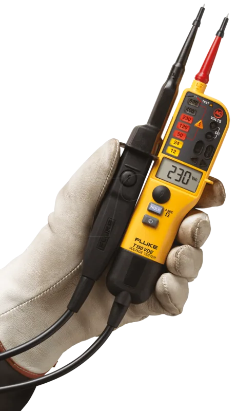
The Fluke T150 VDE Voltage Tester is a compact, rugged voltage and continuity tester designed for electricians and technicians working in industrial, commercial, and residential environments. Combining a clear LED bargraph with an LCD readout (on advanced models) and a range of safety-focused features, the T150 delivers fast visual indication of voltages from low-voltage circuits up to high mains levels. Its slim probe tips, fixed probe cover, and integrated probe-tip protector cap make it convenient for tight spaces and safe storage.
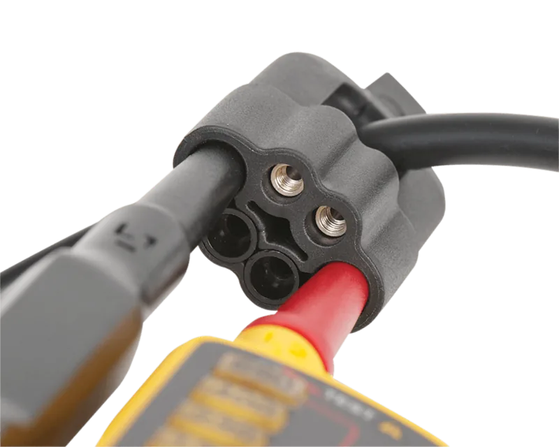
Built to meet strict safety standards, the T150 features CAT III/CAT IV overvoltage protection ratings, IP64 ingress protection, and double-insulated wiring. The unit offers automatic power-on detection above low-voltage thresholds, a visual >ELV indicator that flags voltages above 50 V AC or 120 V DC, and an internal low-impedance mode with a switchable load for RCD trip tests. These options let users reduce interference from capacitive or inductive coupling and verify RCD operation by applying realistic trip currents during measurements.
Beyond basic voltage testing, the T150 provides continuity and diode testing, a low-ohm resistance function (1–1999 Ω) with 1 Ω resolution, and a rotary field indicator for three-phase phase-sequence checks. A useful single-pole phase test and an independent ELV indicator LED ensure rapid detection of live conductors even if batteries fail. Additional conveniences include a torch/backlight for dim workspaces, a beeper (switchable) for continuity and phase indications, and a HOLD function for capturing readings on the LCD.
Ergonomically designed, the tester supports single-handed operation and can be used while wearing gloves. Built-in self-test and clear battery-low indicators help ensure dependable operation before and after use. Accessories such as probe tip sheaths, 4 mm probe extensions, and a holster/carry case improve versatility on the job.
This tester is ideal for electricians who need a portable, safety-certified instrument that handles common tasks—voltage detection, continuity checks, RCD trip testing, and phase sequencing—while providing robust protection and user-friendly features.
Notes
- The >ELV LED warns at >50 V AC or >120 V DC and should not replace true measurement validation. Use the LCD for numeric readings when needed.
- Switchable load (two-button press) is time-limited by overload protection; expect current reduction after ~20 seconds at 230 V.
- Always perform the self-test and verify the beeper/continuity before starting live work.
Search for 67,706 Manuals online


Type-in Brand or Model
Laura Schmidt
10 months ago
Can I switch off the annoying beep or acoustic signal on the Fluke T150/VDE when verifying mains voltage, or is it always on?
Manual.ly
10 months ago
On the Fluke T150/VDE, the acoustic signal is intended as a safety alert and, in this version, it cannot be fully disabled. Users therefore hear the tone during voltage verification and during certain test functions. To reduce distraction, rely on the visual indications on the display/LEDs and the measurement light instead of the sound. If your unit ever behaves unusually, contact support with the device details so it can be checked or replaced under warranty.