

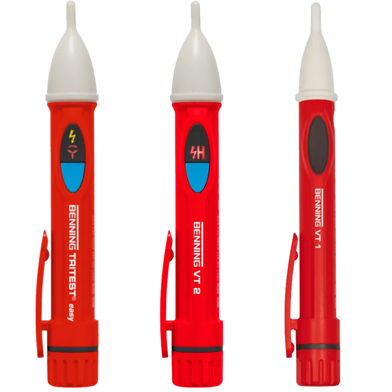

Benning VT 2 Manual
PDF manual · 49 Pages
English



Quick check
Incorrect answer, please try again.
Chat with your Benning VT 2 manual using AI
Get instant AI answers from your Benning VT 2 manual
Ask anything about the Benning VT 2. Answers come from this manual, with the pages they are based on.
VT 2 Maintenance Schedule
Verify the phase indicator and magnetic field tester work correctly immediately before and after every use. Do not use if functions fail.
Replace the two LR03/AAA batteries as soon as the red LED indication or acoustic signal becomes weaker.
Clean the exterior of the device with a clean dry cloth. Also clean the battery area if contamination or deposits are present.
If the device is stored for a longer period of time, remove the batteries from the device to prevent damage.
Ask a Question
Do you recommend VT 2?
Yes NoFrequently Asked Questions
No, the BENNING VT 2 is designed to detect alternating current (AC) fields only. It cannot detect direct current (DC) voltage fields.
Is this answer helpful?
Users with pacemakers or implanted defibrillators should keep a sufficient distance from the device because its internal magnets can affect the functioning of these medical implants.
Is this answer helpful?
You should test the device immediately before and after use. Check the phase function on a known voltage source like a 230 V socket and test the magnetic field function using the integrated test magnet.
Is this answer helpful?
The device requires two Micro batteries, specifically type LR03 or AAA (1.5 V), inserted with the correct polarity.
Is this answer helpful?
No. The BENNING VT 2 is not a substitute for a two-pole voltage tester. You must use a certified two-pole tester to definitively confirm the absence of voltage.
Is this answer helpful?
If the probe tip lights up red and green at the same time, it indicates that both an electrical field from a live part and a magnetic field are being detected simultaneously.
Is this answer helpful?
Advantages and Disadvantages
Advantages

- Detects AC voltages from 12 V to 1000 V without physical contact
- Identifies both electrical and magnetic fields with clear LED and audio feedback
- Includes a built-in test magnet for immediate functional verification
- High sensitivity mode allows detection of low voltages around 12 V AC
- Durable design with IP53 protection against dust and water spray
Disadvantages

- Incapable of detecting DC voltage fields
- Not suitable for confirming zero voltage status compared to two-pole testers
- Magnets inside may interfere with implanted medical devices like pacemakers
- Requires regular battery replacement to maintain optimal performance
- Effectiveness can be reduced by thick insulation or heavy shielding on conductors
Product Specification
Measurement range
12-1000V
Product Description
Benning VT 2 Non-contact Phase Tester – Read, Download & Print Free
The BENNING VT 2 is a versatile non-contact phase indicator and magnetic field tester designed for professional electricians. This device allows users to detect electrical fields generated by AC voltages ranging from approximately 12 volts up to 1000 volts without the need for direct physical contact with live parts. It also features the capability to identify strong magnetic fields produced by electromagnetic switches, relays, and solenoid valves.
Designed with safety as a priority, the BENNING VT 2 operates within specific overvoltage categories (CAT III 1000 V and CAT IV 600 V) and includes a built-in test magnet for verifying functionality before use. The device utilizes a clear LED system where a red light indicates the presence of an electrical field, while a green light signals a detected magnetic field. An acoustic signal accompanies these visual cues, increasing in frequency as the voltage or field strength rises. A special high-sensitivity mode can be activated by holding a blue button, enabling the detection of lower voltages starting around 12 volts AC.
This tool is essential for locating phases in external conductors, identifying interruptions in live cables such as broken wires in cable reels, and checking for magnetic fields in industrial equipment. It does not require current flow during testing, making it a safe option for preliminary checks. However, it is crucial to remember that this device is not a substitute for a two-pole voltage tester when determining the absolute absence of voltage. Users must always follow strict safety protocols, including keeping a safe distance from pacemakers due to the internal magnets, and ensuring the battery compartment is closed during operation.
Important Notes
- Always perform a functional check before and after every use.
- Do not touch the white probe tip during testing; hold only the red handle behind the grip limit.
- Remove batteries if the device will be stored for extended periods to prevent leakage.
- Ensure the device is used only by qualified personnel in accordance with safe working procedures.
Search for 67,706 Manuals online


Type-in Brand or Model
Yvonne Mason
5 months ago
Is this product small enough to be portable and does it fully meet its intended purpose?
Manual.ly
5 months ago
Yes, the product is designed to be compact and practical for easy portability. Based on user feedback, it fully satisfies its primary function and meets customer expectations effectively.