

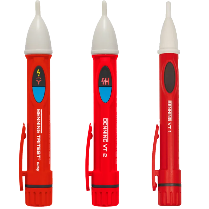

Benning VT 1 Manual
PDF manual · 39 Pages
English



Quick check
Incorrect answer, please try again.
Chat with your Benning VT 1 manual using AI
Get instant AI answers from your Benning VT 1 manual
Ask anything about the Benning VT 1. Answers come from this manual, with the pages they are based on.
VT 1 Maintenance Schedule
Check the device for correct functioning immediately before and after every use using a known voltage source.
Replace batteries when the red LED indication or acoustic signal becomes weak. Use two Micro LR03/AAA batteries.
Clean the exterior of the device with a clean dry cloth. Clean contamination in the battery area with a dry cloth.
If the device is stored for a longer period of time, remove the batteries from the device to prevent damage.
Ask a Question
Do you recommend VT 1?
Yes NoFrequently Asked Questions
No, the BENNING VT1 is designed exclusively for alternating current (AC). It detects electric fields generated by phase voltages starting from approximately 200 V AC. Direct voltage (DC) fields will not be recognized by this device.
Is this answer helpful?
You should replace the batteries immediately if the red LED indicator becomes dim or if the acoustic signal becomes weak. A functional check on a known voltage source is recommended before every use to ensure reliability.
Is this answer helpful?
Yes, provided you follow all safety instructions. The device is rated for CAT III 1000 V and CAT IV 600 V environments. However, it must only be used by qualified electricians, and you must never touch the white probe tip while testing.
Is this answer helpful?
No, you cannot use the BENNING VT1 to confirm the absence of voltage. It only indicates the presence of a phase. To determine if a circuit is de-energized, you must use a certified two-pole voltage tester compliant with DIN EN 61243-3.
Is this answer helpful?
The BENNING VT1 requires two Micro batteries, specifically type LR03 or AAA (1.5 V). They must be inserted with the correct polarity, positive pole facing forward, into the battery compartment.
Is this answer helpful?
Advantages and Disadvantages
Advantages

- Non-contact operation ensures high safety for the user by preventing direct contact with live parts.
- Dual indication system with both visual LED and audible tone provides clear confirmation of phase presence.
- Capable of detecting cable breaks and interruptions in live lines without cutting insulation.
- Always active design with low current consumption extends battery life and readiness for use.
- Robust construction meets CAT III 1000V and CAT IV 600V overvoltage categories for professional environments.
Disadvantages

- Cannot verify the absence of voltage; a separate two-pole tester is required for safety verification.
- Does not detect direct current (DC) voltages, limiting its use to AC systems only.
- Performance can be affected by excessive distance, thick insulation, or heavy shielding around conductors.
- Requires frequent battery replacement when signals weaken, as there is no power switch to turn off.
- Not suitable for unqualified personnel; strictly intended for use by trained electricians.
Product Specification
Measurement range
200-1000V
Product Description
Benning VT1 Non-contact Phase Tester - Read, Download & Print Free
The Benning VT1 Non-contact Phase Tester is an essential tool for qualified electricians who need to quickly and safely identify live phases in electrical installations. Designed with a focus on user safety and reliability, this device allows professionals to detect alternating voltage fields without making direct physical contact with the conductor. This feature significantly reduces the risk of accidental short circuits or electric shocks during routine checks.
Operating within a nominal voltage range of 200 V to 1,000 V AC, the BENNING VT1 responds to frequencies between 45 Hz and 65 Hz. When an electric field is detected, the device provides immediate feedback through a bright red LED located at the probe tip and an audible acoustic signal. The intensity of both the light and sound increases as the voltage strength rises, giving the operator a clear indication of the presence and magnitude of the phase voltage.
Beyond simple phase detection, the Benning VT1 serves as a cable break detector. By sliding the probe along an insulated line from the power source towards the end, users can locate interruptions such as broken wires in cable reels or defective bulbs in lighting chains. The moment the signal stops, the exact location of the break has been found. It is important to note that this device does not confirm the absence of voltage; it only indicates presence. For verifying that a circuit is truly dead, a two-pole voltage tester must be used.
Safety is paramount in the design of this instrument. It features a protective insulation class II construction and includes a grip limit to ensure hands never touch the sensitive white probe tip during operation. The unit is always active, utilizing a special low-power circuit to maximize battery life, though it requires fresh AAA batteries to function correctly. With its compact dimensions and lightweight build, it fits easily into any toolkit while meeting rigorous industrial standards like DIN EN 61010-1.
Important Notes
- Always perform a functional test on a known live source before and after using the device.
- Do not use the tester if the battery compartment is open or if indicators are weak.
- The device cannot detect DC voltage fields.
- Ensure proper distance from the conductor; thick insulation or shielding may prevent detection.
Search for 67,706 Manuals online


Type-in Brand or Model
Kayleigh Altenwerth
7 months ago
Does the side-specific shutdown check function reliably?
Manual.ly
6 months ago
Yes, the side-specific shutdown check feature is designed to work effectively. Users have confirmed that it accurately verifies the shutdown status on each side, ensuring proper operation and safety.