Manual.ly Logo

Voltcraft VC-13A Manual

4.0 · 2 Ratings

PDF manual · 12 Pages

English

M: QW-35-FL
page

/ 12

Loading...
e150e37db53ef651200c1138b7cf35b312de page 5
c) Resistance measurement
Make sure that all the circuit parts, switches and components and other objects to be
measured are disconnected from the voltage and discharged at all times.
Proceed as follows to measure resistances:
• Select the measuring function “Ω” with the rotary switch .
• Connect the black measuring line to the COM socket (5) and the red measuring line to the socket “Ω” (6).
• Touch the two measuring tips to each other and wait until the pointer has stabilised. A value of approx.
0 Ohm must be displayed. In case of a deviation, adjust the pointer with the 0 Ohm calibration control (3)
to 0 Ohm. Always check this when changing the measuring range.
• Read off the measuring value on the scale “Ω”.
• In the “x1k” measurement range, multiply the displayed value by a factor of 1000 to get the measured
value e. g. 5 Ω (display) x 1000 = 5 x 1000 = 5 kΩ (measured value).
• In the “x10” measurement range, multiply the displayed value by a factor of 10 to get the measured value
e. g. 50 Ω (display) x 10 = 50 x 10 = 500 Ω (measured value).
• After completing the measurement, remove the measuring tips from the measuring circuit and switch the
multimeter off (rotary switch position: “OFF”).
d) Direct current measurement
Never exceed the max. permitted input values in the respective measuring ranges.
Current measuring operations are permissible only in circuits up to max. 300 V.
Proceed as follows to measure direct currents up to 250 mA/DC voltages:
• Select the measuring function “mA” with the rotary switch .
• Connect the black measuring line to the COM socket (5) and the red measuring line to the socket “mA” (6).
• Disconnect the object to be measured from the mains.
• Pay attention to the correct polarity (red = + / black = -) and connect the two measuring tips in series with
the measuring object (battery, circuit, etc.).
• In the case of a pole reversal, the needle deects in the negative direction. This could damage the meter
mechanism. Stop the measurement at once and repeat the measurement with the correct polarity.
• Read off the measuring value on the scale “mA”.
• Disconnect the measured object from the mains and remove the measuring tips from the measuring
circuit after the measurement is completed. Switch off the multimeter (rotary switch position “OFF”).
e) Attenuation measurement in dBm
The multimeter enables absolute “dB” measuring in circuits with an impedance of 600 Ohm. Measurements
are made in the “10 V~” range. 0 dB = 1 mW (0.775 V).
Proceed as follows for the measurement:
• With the rotary switch, select the measuring range “10 V~“.
• Connect the black measuring line to the COM socket (5) and the red measuring line to the socket “V” (6).
• Now connect the two measuring probes in parallel to the object to be measured (generator, switch, etc.).
• Read off the measured value on the scale “dB”. Read the voltage on the scale “AC10V”.
• If signals with a direct voltage ratio are to be measured, a capacitor of >0.1nF must be connected in
series to the measuring lines (decoupling).
• After completing the measurement, remove the measuring tips from the measuring circuit and switch the
multimeter off (rotary switch position: “OFF”).
f) Battery test
The multimeter tests 1.5 V or 9 V batteries with a low load. This prevents faulty measurements during
open-circuit operation and gives signicant clues to the battery condition.
"REPLACE" indicates that the battery must be replaced.
"?" indicates that the battery can still be used only for low power consumer loads.
"GOOD" indicates that the battery is OK.
To test the batteries, proceed as follows:
• With the rotary switch select the measuring function “BAT” and the measuring range 1.5 V or 9 V.
• Connect the black measuring line to the COM socket (5) and the red measuring line to the socket “V” (6).
• Pay attention to the correct polarity (red = + / black = -) and connect the two measuring tips to the
battery.
• In the case of a pole reversal, the needle deects in the negative direction. This could damage the meter
mechanism. Stop the measurement at once and repeat the measurement with the correct polarity.
• Read off the measured value on the scale “BAT”.
• After completing the measurement, remove the measuring tips from the measuring circuit and switch the
multimeter off (rotary switch position: “OFF”).
CLEANING AND MAINTENANCE
General information
To ensure the accuracy of the multimeter over an extended period of time, it should be calibrated once a
year.
Information on changing the battery and fuse appears below.
Regularly check the technical safety of the device and the measuring cables, e.g. for
damage to the housing or crimping, etc.
Never operate the meter when it is open. ! RISK OF FATAL INJURY!
EXPLANATION OF SYMBOLS AND SIGNS
Overload, the resistance measuring range was exceeded
Symbol for the built-in battery data
Symbol for the built-in fuse
OFF Switch position OFF
COM Measurement reference potential, - for DC
VmAΩ Measurement input for measurement potential, + for DC
AC Symbol for alternating current
DC Symbol for direct current
V Volt (unit of electric voltage)
mA Milliampere (unit of electric current, exp.-3)
Ω Ohm (unit of electrical resistance)
x10 The resistance value read must be multiplied by 10
x1k The resistance value read must be multiplied by 1000
dB
Decibels, attenuation in the 10 V AC voltage measurement circuit
(0 dB = 1 mW/600 Ohm = 0.775 V)
BAT Battery test
9 V/1.5 V Measurement range for batteries with 9 V or 1.5 V nominal voltage
REPLACE The tested battery must be replaced
? The tested battery should be replaced as soon as possible
GOOD The tested battery can be used
START-UP
Before you can work with the measuring device in the resistance measurement range, you must
rst insert the enclosed battery. Insert the battery as described in the chapter “Cleaning and Mainte-
nance”.
Rotary switch (4)
• The individual measuring functions and ranges can be set using the rotary switch.
• If the rotary switch is set to “OFF”, the measuring device is switched off.
• Always turn the meter off when it is not in use.
• An automatic cut-off does not occur in the resistance range.
WEIGHING
Do not exceed the maximum permitted input values under any circumstances. Never
touch circuits or parts of circuits when they may contain voltages greater than
33 V/ACrms or 70 V/DC! Risk of fatal injury! Before every measurement, check the
meter and the connected measuring leads for damage such as cuts, cracks or pinches.
Remove defective measuring leads immediately and replace them with new measuring
cables. Defective measuring leads must no longer be used. ! Risk of fatal injury!
Before changing the measuring range, the test probes have to be removed from the
measured object.
Always start each measurement with the largest measuring range. Then gradually
change to a smaller one to achieve an exact measured result. The best precision occurs
in the mid-scale range (scale range ca. 70° to 110°).
The measuring results at the rotary switch correspond to the scale end value. For reading, always select
the corresponding value (e.g. scale 10 for the measuring range 10).
a) Zero adjustment
Before each measurement, adjust the zero position with the calibration screw (2) (scale value 0 V). There
must be no measuring signal on the measuring lines.
b) Measuring AC and DC voltages
Do not exceed the maximum permitted input values under any circumstances.
Proceed as follows to measure direct current (DC) voltages:
• Select the measuring function V with the rotary switch .
• Connect the black measuring line to the COM socket (5) and the red measuring line to the V socket (6).
• Pay attention to the correct polarity (red = + / black = -) and connect the two measuring tips in parallel to
the object to be measured (battery, circuit, etc.).
• In the case of a pole reversal, the needle deects in the negative direction. This could damage the meter
mechanism. Stop the measurement at once and repeat the measurement with the correct polarity.
• Read off the measured value on the scale “V”.
DC V range V scale for reading Multiplier
2.5 0 - 250 0.01
10 0 - 10 1
50 0 - 50 1
250 0 - 250 1
300 0 - 300 1
• After completing the measurement, remove the measuring tips from the measuring circuit and switch the
multimeter off (rotary switch position: “OFF”).
Proceed as follows to measure AC voltages:
• Select the measuring function V with the rotary switch .
• Connect the black measuring line to the COM socket (5) and the red measuring line to the V socket (6).
• Now connect the two measuring probes in parallel to the object to be measured (generator, switch etc.).
• Read off the measured value on the scale “V”.
• After completing the measurement, remove the measuring tips from the measuring circuit and switch the
multimeter off (rotary switch position: “OFF”).

Chat with your Voltcraft VC-13A manual using AI

Get instant AI answers from your Voltcraft VC-13A manual

Ask anything about the Voltcraft VC-13A. Answers come from this manual, with the pages they are based on.

VC-13A Maintenance Schedule

Remind me when maintenance is due
Yearly
Calibrate the multimeter

To ensure accuracy over an extended period, the manual recommends calibrating the device once a year.

Regularly
Inspect device and leads for damage

Regularly check the technical safety of the device and measuring cables for housing damage or crimping.

Free maintenance reminders

Timed to your purchase date. Always free, unsubscribe anytime.

By submitting you agree to the privacy policy. Unsubscribe with one click in any email.
M: qwen/qwen3.8-flash

Ask a Question

0/1000

Do you recommend VC-13A?

Yes No
0
User Pic

anderson47

6 months ago

Is it safe to use a slower fuse with a higher voltage rating if the original fast-blow fuse is unavailable?

0
User Pic

Manual.ly

6 months ago

While using a substitute fuse may allow the device to function temporarily, it is not recommended for long-term safety. The original fuse rating ensures proper protection against overcurrent. Using a higher voltage or slower fuse could compromise safety in case of an electrical fault. We advise sourcing the correct 500V fast-blow fuse before regular use.

M: QW-35-FL
M: QW-35-FL
0
User Pic

Nikki Ross

4 months ago

Does the compact size and easy-to-read scale make this tool suitable for beginners?

M: QW-35-FL

Frequently Asked Questions

A

No, do not operate the multimeter in damp rooms, under high humidity, or when wet. Moisture can compromise safety and damage the device.

Is this answer helpful?

A

It requires one Mignon battery, specifically Type AA (UM3, LR6, or equivalent) with a voltage of 1.5 V.

Is this answer helpful?

A

Short the probes together, wait for the needle to stabilize, and adjust the 0-Ohm control to zero before measuring the component.

Is this answer helpful?

A

Yes, it is rated CAT III up to 300 V, making it suitable for household electrical installations and general hobbyist tasks.

Is this answer helpful?

A

Stop immediately, disconnect the probes, and check your polarity. Reverse the red and black leads to correct the connection.

Is this answer helpful?

A

No, unauthorized modification or conversion is strictly prohibited for safety and approval reasons (CE).

Is this answer helpful?

A

To ensure accuracy over time, the device should be calibrated at least once a year.

Is this answer helpful?

M: QW-35-FL

Advantages and Disadvantages

Advantages

  • Shock-absorbing pointer instrument works in any orientation
  • Includes built-in battery test for 1.5 V and 9 V cells
  • Measurement Category III rated up to 300 V for safe building installation work
  • Ceramic fuse protects the mA current range from overloads
  • Calibration screw allows for precise zero adjustment before use
VS

Disadvantages

  • No automatic power-off feature in resistance mode
  • Requires manual zero adjustment for accurate readings
  • Not suitable for measuring voltages exceeding 300 V safely
  • Cannot be used in explosive atmospheres or damp rooms
  • Manual operation requires user attention to polarity and ranges
M: QW-35-FL

Product Specification

Measurement Range

max. 300V, max. 2MΩ

Package Contents

Test Leads

M: QW-35-FL

Product Description

Voltcraft VC-13A Analog Multimeter Review

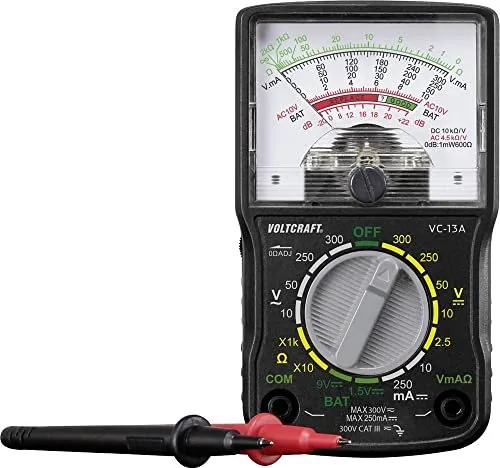
The Voltcraft VC-13A Analog Multimeter is a robust and reliable tool designed for both hobbyists and professionals who require precise electrical measurements in a portable format. This device features a shock-absorbing pointer instrument that allows for readings in any operating position, making it ideal for tight spaces or awkward angles where digital displays might be hard to read. The multimeter supports Measurement Category III up to 300 V, ensuring safety during use in building installations like sockets and sub-distributions.

Equipped with a rotary switch, users can easily select between various functions including direct current (DC), alternating current (AC), resistance, and attenuation measurements. The mA current range is protected by a ceramic fuse against overload, adding an extra layer of safety. Before every measurement, the scale pointer can be adjusted using the calibration screw to ensure accuracy and prevent reading errors. The device also includes a dedicated battery test function for 1.5 V and 9 V batteries, providing clear indicators like "GOOD," "?" or "REPLACE" to assess battery health without needing external testers.

Safety is paramount with this unit. It complies with CE standards and features double insulation. Users are advised to avoid measuring voltages above 33 V AC or 70 V DC unless they are trained professionals. The device must never be operated with an open casing or missing battery cover to prevent fatal electric shocks. Additionally, it should not be used during thunderstorms or in environments with flammable gases. Regular maintenance, such as annual calibration and checking for damaged leads, ensures long-term reliability. The package includes the multimeter, test leads, an AA battery, and comprehensive instructions available online.

Key Features and Usage Notes

This analog meter excels in simplicity and durability. The large scale display makes it easy to observe trends and fluctuations in real-time. When measuring resistance, remember to zero the meter by shorting the probes and adjusting the 0-Ohm control. Always start measurements on the highest range and work down for better precision. Keep the device dry and away from strong magnetic fields to avoid distorted readings.

M: QW-35-FL

© Copyright 2026 Manual.ly