Manual.ly Logo

Doepke DRCCB 5 STR Manual

0.0 · 0 Ratings

PDF manual · 5 Pages

English

M: OA-GPT-5-NAN
page

/ 5

Loading...
f80ed3b13d7fce27b454aa838ea185dba8f8 page 4
LED ashing codes
Selftest/Selftest Restart o (slider moved right to position AUTO OFF)
LED 1 LED 2
Toggle
position
Auxiliary contact
  Up
On after

  Down 
Yellow  Up On Electronics fault
Yellow  Down On Electronics fault
  Up On
! No residual current
protection

  Down On
! No residual current
protection

Selftest Restart on (slider moved left to position AUTO ON):
LED 1 (red/
yellow)
LED 2
(green)
Toggle
position
Auxiliary
contact
 On Up 
On Down  System check
On Up  Selftest
On Down On Locked
Yellow On Up On Electronics fault
Yellow On Down On Electronics fault
On Up On
! No residual current
protection

On Down On
! No residual current
protection

On Down On Service mode
Selftest on (slider moved left to position AUTO ON):
LED 1
(red/yellow)
LED 2
(green)
Toggle
position
Auxiliary
contact
 On Up 
On Up  Selftest
On Down On Trip
Yellow On Up On Fault
Yellow On Down On Fault
On Up On
! No residual current
protection

LED 1
(red/yellow)
LED 2
(green)
Toggle
position
Auxiliary
contact
On Down On
! No residual current
protection

Selftest Restart:
 
 
 Locked = LED 1 continuously red
 

Selftest:
 
 Tripped = LED 1 continuously red
 

! If LED 1 is illuminated yellow, try performing an automatic test of the RCCB
by using the SET button. If LED 1 remains illuminated yellow contact a specia-
lised technician.
Functional overview
Selftest
Selftest
restart
Automatic
selftest (uninterruptible power supply)
3 3
Display: selftest in progress
3 3
Display: selftest

3 3
Automatic restart
when trip occurs
3
Insulation resistance measurement
3
Constant system check
3
Restart function lock in the event of a fault
3
Display: restart in progress
3
Display: fault
3
Automatic restart function can be toggled

3
Auxiliary contact for remote signalling
3
Overcurrent protection PTC
Warranty
All professionally installed, unaltered devices are covered by warranty during
the statutory warranty period from the day of purchase by the end user. The
warranty is not applicable to damage incurred during transport or caused by
short-circuit, overloading or improper use. In the event of defects in workman-
ship or material being discovered within the warranty period, the company will
provide a repair or replacement free of charge. The warranty will be rendered
null and void if the device is opened without authorisation.
Dimensional drawings
106
90
17,8
6
44
73,5
7,4
45
V two-pole
Mode 1: NO normally opened (make contact)




Press and hold the SET key for at least 5 s > then release

Press and hold the SET key for at least 5 s > then release

Press and hold the SET key for at least 5 s > then release

Pulse diagram for auxiliary contact
Note

(± 20%) every 3 hours (± 20%) in order to perform a check of the electronics.
Flow diagram for selftest/selftest restart
Function test of automatic reset (selftest
restart)
Once the operating voltage (1) is switched on
the device must be tripped manually by press-
ing the test button T (3). Press the button by
inserting a screwdriver into the corresponding
opening on the slider (5).
If the reset cycle is not performed correctly,
the insulation resistance of the system must
be checked.
Selftest and manual tripping
When the operating voltage (1) is on, the auto-
matic selftest for the residual current circuit-
breaker is performed monthly without inter-
rupting the system's power supply, as soon as
the slider is moved left to position AUTO ON
(2). The test can also be triggered manually
by pressing the SET key (3). The timer for the
monthly test is started when the operating
voltage (1) is on or when the SET key is pressed.
LED displays
SET
LED 1
rot/gelb
red/yellow
LED 2
grün
green
Auslösung
Anlagen-
kontrolle
Test
OK?
Wiedereinschaltung
Hilfskontakt
aktiviert
Bereitschaft
Anlagen-
kontrolle
Test
OK?
LED 1
:
rot LED 1
:
rot
ja
nein
ja
LED 1
:
rot
tripped
system
control
re- closing
auxiliary contact
activated
standby
LED 1
:
red LED 1
:
red
yes
no
yes
LED 1
:
red
system
control
Conguring the auxiliary contact

moved left to position AUTO ON (I).
       
holding the SET key for at least 5 s. The switch be-


SET
EIN
ON
SET
SET
1
EIN
ON
2
3
CLACK
SET
0,5 s 0,5 s 0,5 s0,5 s 0,5 s
Selbsttest
ausgelöst
1 s
gelb
yellow
Selftest
5
6
7
rot
red
rot
red
rot
red
rot
red
0,5 s 0,5 s 0,5 s0,5 s 0,5 s
Anlagenkontrolle/Selbsttest
5 s5 s5 s
Wartemodus
blockiert
1 s
0,25 s
kein Fehlerstromschutz
0,15 s
gelb
yellow
gelb
yellow
rot
red
0,15 s
rot
red
rot
red
rot
red
rot
red
LED 1
1
2
3
4
rot
red
LED 1
LED 1
Selftest - Restart
0,25 s
0,15 s
gelb
yellow
rot
red
0,15 s
rot
red
LED 1
LED 1
LED 1
0,25 s
0,15 s
0,15 s
0,25 s
0,15 s
0,15 s
system control/Selftest
waiting mode
blocked
no residual current protection
Selftest
tripped
kein Fehlerstromschutz
no residual current protection
1
2
3
Fehler
Error
3 h (± 20 %)
Electronic - check
Fehler
Error
3 h (± 20 %)
NO
NC
NC
+
Fehler
Error
500 ms (± 20 %)
3 h (± 20 %)
positive self - diagnosis
Elektroniktest
Electronic - check
Elektroniktest
Erfolgreicher Selbstest
100 ms (± 20 %)
500 ms (± 20 %)
500 ms (± 20 %)
230V~
2
LED ON
4
3
CLACK
5
1
ON
SET
SET
SET
SET
0,5 s 0,5 s 0,5 s0,5 s 0,5 s
Selbsttest
ausgelöst
1 s
gelb
yellow
Selftest
5
6
7
rot
red
rot
red
rot
red
rot
red
0,5 s 0,5 s 0,5 s0,5 s 0,5 s
Anlagenkontrolle/Selbsttest
5 s5 s5 s
Wartemodus
blockiert
1 s
0,25 s
kein Fehlerstromschutz
0,15 s
gelb
yellow
gelb
yellow
rot
red
0,15 s
rot
red
rot
red
rot
red
rot
red
LED 1
1
2
3
4
rot
red
LED 1
LED 1
Selftest - Restart
0,25 s
0,15 s
gelb
yellow
rot
red
0,15 s
rot
red
LED 1
LED 1
LED 1
0,25 s
0,15 s
0,15 s
0,25 s
0,15 s
0,15 s
system control/Selftest
waiting mode
blocked
no residual current protection
Selftest
tripped
kein Fehlerstromschutz
no residual current protec
tion
Doepke

|

|

DE EN


Chat with your Doepke DRCCB 5 STR manual using AI

Get instant AI answers from your Doepke DRCCB 5 STR manual

Ask anything about the Doepke DRCCB 5 STR. Answers come from this manual, with the pages they are based on.

DRCCB 5 STR Maintenance Schedule

Remind me when maintenance is due
Monthly
Run the automatic RCCB selftest

With AUTO ON selected, the device performs an uninterrupted automatic selftest. The monthly timer starts when operating voltage is applied or SET is pressed.

Every 2 minutes after a trip
Measure insulation resistance after a trip

For the Selftest Restart version, insulation resistance is measured after a trip. The device automatically restarts when a safe resistance value is reached.

Every 3 hours
Check the auxiliary-contact electronics

The auxiliary contact opens for 500 ms to perform an electronics check, regardless of its configuration.

Free maintenance reminders

Timed to your purchase date. Always free, unsubscribe anytime.

By submitting you agree to the privacy policy. Unsubscribe with one click in any email.
M: gpt-5.6-terra

Ask a Question

0/1000

Do you recommend DRCCB 5 STR?

Yes No

Frequently Asked Questions

A

The DRCCB 5 STR is a Type A residual current circuit breaker that performs monthly selftests without interrupting supply and, after a trip, measures insulation resistance to permit controlled automatic reclosing when safe.

Is this answer helpful?

A

Move the slider to AUTO ON (left). This activates the monthly uninterruptible selftest and, for the STR variant, enables the automatic reclosing cycle that performs insulation checks before restarting.

Is this answer helpful?

A

Press the SET button to initiate an automatic test. If LED 1 remains yellow after the test, a qualified technician should inspect the device and the installation for faults or electronic issues.

Is this answer helpful?

A

No. Due to safety risks and regulatory requirements, installation and configuration must be performed by qualified electricians. Automatic reclosing is permitted only in restricted areas per DIN VDE 0100-530.

Is this answer helpful?

A

The DRCCB 5 STR snaps onto an EN 60715 DIN mounting rail. Feed-in must come from the top and all active conductors plus the neutral must be routed through the breaker following the provided wiring diagram.

Is this answer helpful?

A

It uses two LEDs (LED 1 red/yellow and LED 2 green) with defined blink codes for selftest, insulation checks, trips, blocked restart and faults. An auxiliary contact provides remote pulses after successful selftests and status signaling.

Is this answer helpful?

A

After a trip the STR variant measures insulation resistance every two minutes; if the resistance reaches the configured safe threshold the device will automatically attempt reclosing, unless blocked by fault conditions or restart counters.

Is this answer helpful?

M: OA-GPT-5-NAN

Advantages and Disadvantages

Advantages

  • Monthly uninterruptible selftest maintains protection without cutting supply
  • Automatic reclosing after insulation check reduces downtime where allowed
  • Clear LED blink codes and SET/manual test functions aid diagnostics
  • Auxiliary contact for remote signaling and integration with building systems
  • DIN-rail mounting and top feed-in simplify professional installation
VS

Disadvantages

  • Automatic restart allowed only in areas with trained electrical personnel (DIN VDE)
  • Not suitable for environments with corrosive gases—may impair long-term function
  • Automatic reclosing can mask persistent insulation problems if not monitored
  • Installation and configuration require qualified electricians; not DIY-friendly
  • Complex LED codes and modes may require consulting manual for full interpretation
M: OA-GPT-5-NAN

Product Specification

Type

RCCB

Rated Voltage

400 V

Residual Current Type

A

Degree of Protection

IP20

Special Features

short-time delayed

M: OA-GPT-54-NAN

Product Description

Doepke DRCCB 5 STR — Reliable self-testing RCCB with auto-restart

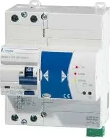
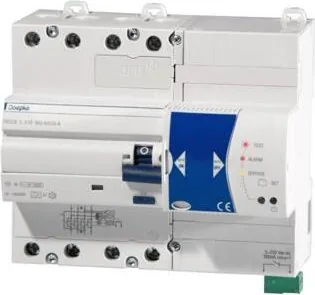
The Doepke DRCCB 5 STR is a two-/four-pole Type A residual current circuit breaker (RCCB) designed for modern electrical installations that require continuous safety monitoring and automatic restoration after a trip. Built around a monthly uninterruptible selftest and an automatic reclosing function, the DRCCB 5 STR combines fault detection, insulation monitoring and controlled restart logic to reduce downtime while keeping people and equipment protected.

Featuring a dedicated Selftest Restart mode, the device measures insulation resistance periodically after a trip and attempts automatic reclosing only when the measured resistance meets preset safety thresholds. This makes it particularly suitable for installations where selective automatic recovery is desired—such as industrial subcircuits, critical building services and restricted-access electrical rooms where only trained personnel are present.

Practical controls and status indicators include a slider to enable/disable automatic testing and restart (AUTO ON / AUTO OFF), a SET button to initiate manual tests, and multi-color LED signaling for selftest progress, system checks, faults, trips and blocked restart conditions. An auxiliary remote contact reports test pulses and status changes for building automation or remote monitoring systems.

Installation is straightforward for qualified electricians: the unit snaps onto EN 60715 DIN rail, requires top feed-in, and all active conductors plus neutral must be routed through the device as per the wiring diagram. The DRCCB 5 STR complies with relevant standards and includes PTC overcurrent protection for auxiliary contacts, clear LED blink codes for diagnostics, and configuration options via the SET key (long press cycles through modes). Safety notes stress operation only in corrosive-gas-free environments and prohibit installation by non-qualified personnel.

Key user interactions are simple: after power-up move the slider to AUTO ON to enable automatic monthly selftests and restart behaviour; press the SET button to force a manual selftest; use the test (T) opening to verify trip operation. If LED 1 shows persistent yellow, perform the automatic test via SET and consult a technician if it remains yellow.

Overall, the Doepke DRCCB 5 STR targets installations where both automatic self-diagnostics and cautious automatic reclosing are required, balancing protection and availability while giving installers clear diagnostic feedback.

Notes

  • Only qualified electricians should install and configure the device. Follow DIN VDE and local rules for automatic restart permissions.
  • Avoid use in atmospheres with corrosive gases (chlorine, ammonia, sulfur).
  • Keep the wiring diagram and installation instructions available for maintenance.
M: OA-GPT-5-NAN

© Copyright 2026 Manual.ly