Manual.ly Logo

Doepke DRCCB 5 STR Manual

0.0 · 0 Ratings

PDF manual · 5 Pages

English

M: OA-GPT-5-NAN
page

/ 5

Loading...
f80ed3b13d7fce27b454aa838ea185dba8f8 page 3
106
124,8
17,8
6
44
73,5
7,4
45
V vierpolig
Anschlussschema
1
N
2
N
Lastseite
load-circuit
1
N
3
5
2
N
4
6
Lastseite
load-circuit
V zweipolig
Technische Daten
Typ Selftest / Selftest
Restart zweipolig
Selftest / Selftest
Restart vierpolig
Elektrische Eigenschaften
Normen
Selftest: EN 61008-1,
VDE V 0664-120 (Anhang M)
Selftest Restart:
EN 61008-1, EN 50557
Netzform
Selftest: TT-TN-IT
Selftest Restart: TT-TN
Bemessungsspannung (Ue) 


mindest Betriebsspannung
(Ue min)

maximale Betriebsspannung
(Ue max)

Bemessungs-
isolationsspannung (Ui)

Isolationsfestigkeit 
Bemessungsstoßspannungs-
festigkeit ( Uimp)

Bemessungsfrequenz 
Bemessungsfehlerschalt-
vermögen (IΔm)

Kurzschlussfestigkeit des
Fehlerstromschutzschalters in
Verbindung mit Sicherungen
(IΔc)


Anzahl Pole
Typ Selftest / Selftest
Restart zweipolig
Selftest / Selftest
Restart vierpolig
Typ der
Fehlerstromschutz einrichtung
A
kurzzeitverzögert ja
Stoßstromfestigkeit 
|

Bemessungsstrom (In) 
Bemessungsfehlerstrom (IΔn)  
Widerstand gegen Erde für
Sperren der Wiedereinschal-
tung (Rdo)

(nur Selftest
Restart)

Selftest Restart)

Selftest Restart)
Widerstand gegen Erde für
Freigabe der Wiederein-
schaltung (Rd)

(nur Selftest
Restart)

Selftest Restart)

Selftest Restart)
Stromwärmeverluste pro
Strombahn bei In






Leistungsaufnahme
im Normalbetrieb

Leistungsaufnahme während
der Wiedereinschaltung

Wiedereinschaltfunktion automatisch (nur Selftest Restart)
Einspeisung oben
Mechanische Eigenschaften
Anzahl Teilungseinheiten
Dauer Wiedereinschaltung 
Dauer Selbsttest 
 
mechanische Schaltspiele
(Anzahl Wiedereinschaltungen)

maximale Anzahl aufeinan-
derfolgende Wiedereinschalt-
versuche


Zählerrückstellzeit für
aufeinanderfolgende
Wiedereinschaltversuche

Anschluss 

massiv
Anzugsdrehmoment 
Schutzart 
Umgebungstemperatur


Klimafestigkeit 
Eigenschaften Hilfskontakt
Kontakttyp Photomos
Betriebsspannung 
Maximalstrom 
Minimalstrom 
Frequenz 
Gebrauchskategorie 
Kontaktart 

Anschluss 
Anzugsdrehmoment 
Legende:
 230 V Phase – Neutralleiter
 bei fehlerfreier Anlage
 
 Kontakt schaltet nach jedem erfolgreichen Selbsttest für 100 ms (± 20%) um.
V vierpolig
f +
ARD
N
L3
L2
L1
N
Lastseite / load-circuit
AUX
V four-pole, ARD (automatic reclosing device)
Testing and functional check (Selftest and Selftest restart)
After switching on the operating voltage (1) move the toggle to position I (2).
The automatic test cycle is activated as soon as the slider is moved left to posi-
tion AUTO ON, so that the toggle is completely covered (3). The green LED
illuminates (4).
Automatic operation is deactivated as soon as the slider is moved right to posi-

SET
SET
CLACK
3
LED EIN
LED ON
4
2
2
4
5
LED AUS
LED OF
F
6
1
EIN
ON
1
EIN
ON
3
SET
SET
SET
SET
SET
SET
Selftest/Selftest Restart EIN/ONSelftest/Selftest Restart AUS/OFF
Manual functional check (Selftest and Selftest restart)
When the operating voltage (1) is on and once automatic operation (2) is deacti-
vated and test button T (3) is pressed, the device must trip (4).
SET
SET
CLACK
3
LED EIN
LED ON
4
2
2
4
5
LED AUS
LED OF
F
6
1
EIN
ON
1
EIN
ON
3
SET
SET
SET
SET
SET
SET
Selftest/Selftest Restart EIN/ONSelftest/Selftest Restart AUS/OFF
Installation and operating instructions
for two/four-pole residual current circuit
breakers DRCCB 5 ST and DRCCB 5 STR
-
ists. The installation of devices of this type is not appropriate for electrical lay-
persons due to the considerable potential dangers. The installation and operat-
ing instructions must be kept so that it can be referred to at a later stage. The
operator of the electrical system must be informed about the application and
function of this protective device.
Application instructions and warnings
 Devices with visible damage must not be installed or used.
 Operation must only occur under normal ambient conditions free of corro-
sive gases in order to preserve the correct tripping function in the long term.
Corrosive gases include chlorine, ammonia and sulphur.
 Erroneous tripping due to operation related leakage currents or atmospher-
ic interference cannot be ruled out with absolute certainty.
           -
stream installation.
 According to standard DIN VDE 0100-530, automatic restart is only permit-
ted in areas where only trained electricians have access.
Intended use and installation
Series DRCCB 5 protective devices are type A pulsating AC-DC sensitive resid-
ual current circuit-breakers (RCCBs) which perform a monthly selftest without
interrupting the power supply. They are used to protect electrical systems by

DRCCB 5 ST (selftest): A monthly selftest is performed without interrupting
the power supply.
DRCCB 5 STR (selftest restart): A monthly selftest is performed without inter-
rupting the power supply. The insulation resistance is also measured every two
minutes after a trip (system check). If this resistance reaches a safe value, the
system is automatically restarted.
Installation notes
The device is snapped onto a mounting rail in accordance with EN 60715. The
connection must be made in accordance with the wiring diagram. Guide all ac-
tive conductors and the neutral conductor through the circuit breaker. Supply
must come from the top.
N
T
f +
ARD
N
L
Lastseite / load-cicuit
AUX
V two-pole, ARD (automatic reclosing device)
SET
AUX
Doepke Doepke

|

|
 
|

|

DE ENDE EN

Chat with your Doepke DRCCB 5 STR manual using AI

Get instant AI answers from your Doepke DRCCB 5 STR manual

Ask anything about the Doepke DRCCB 5 STR. Answers come from this manual, with the pages they are based on.

DRCCB 5 STR Maintenance Schedule

Remind me when maintenance is due
Monthly
Run the automatic RCCB selftest

With AUTO ON selected, the device performs an uninterrupted automatic selftest. The monthly timer starts when operating voltage is applied or SET is pressed.

Every 2 minutes after a trip
Measure insulation resistance after a trip

For the Selftest Restart version, insulation resistance is measured after a trip. The device automatically restarts when a safe resistance value is reached.

Every 3 hours
Check the auxiliary-contact electronics

The auxiliary contact opens for 500 ms to perform an electronics check, regardless of its configuration.

Free maintenance reminders

Timed to your purchase date. Always free, unsubscribe anytime.

By submitting you agree to the privacy policy. Unsubscribe with one click in any email.
M: gpt-5.6-terra

Ask a Question

0/1000

Do you recommend DRCCB 5 STR?

Yes No

Frequently Asked Questions

A

The DRCCB 5 STR is a Type A residual current circuit breaker that performs monthly selftests without interrupting supply and, after a trip, measures insulation resistance to permit controlled automatic reclosing when safe.

Is this answer helpful?

A

Move the slider to AUTO ON (left). This activates the monthly uninterruptible selftest and, for the STR variant, enables the automatic reclosing cycle that performs insulation checks before restarting.

Is this answer helpful?

A

Press the SET button to initiate an automatic test. If LED 1 remains yellow after the test, a qualified technician should inspect the device and the installation for faults or electronic issues.

Is this answer helpful?

A

No. Due to safety risks and regulatory requirements, installation and configuration must be performed by qualified electricians. Automatic reclosing is permitted only in restricted areas per DIN VDE 0100-530.

Is this answer helpful?

A

The DRCCB 5 STR snaps onto an EN 60715 DIN mounting rail. Feed-in must come from the top and all active conductors plus the neutral must be routed through the breaker following the provided wiring diagram.

Is this answer helpful?

A

It uses two LEDs (LED 1 red/yellow and LED 2 green) with defined blink codes for selftest, insulation checks, trips, blocked restart and faults. An auxiliary contact provides remote pulses after successful selftests and status signaling.

Is this answer helpful?

A

After a trip the STR variant measures insulation resistance every two minutes; if the resistance reaches the configured safe threshold the device will automatically attempt reclosing, unless blocked by fault conditions or restart counters.

Is this answer helpful?

M: OA-GPT-5-NAN

Advantages and Disadvantages

Advantages

  • Monthly uninterruptible selftest maintains protection without cutting supply
  • Automatic reclosing after insulation check reduces downtime where allowed
  • Clear LED blink codes and SET/manual test functions aid diagnostics
  • Auxiliary contact for remote signaling and integration with building systems
  • DIN-rail mounting and top feed-in simplify professional installation
VS

Disadvantages

  • Automatic restart allowed only in areas with trained electrical personnel (DIN VDE)
  • Not suitable for environments with corrosive gases—may impair long-term function
  • Automatic reclosing can mask persistent insulation problems if not monitored
  • Installation and configuration require qualified electricians; not DIY-friendly
  • Complex LED codes and modes may require consulting manual for full interpretation
M: OA-GPT-5-NAN

Product Specification

Type

RCCB

Rated Voltage

400 V

Residual Current Type

A

Degree of Protection

IP20

Special Features

short-time delayed

M: OA-GPT-54-NAN

Product Description

Doepke DRCCB 5 STR — Reliable self-testing RCCB with auto-restart

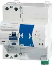
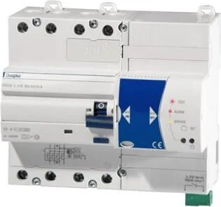
The Doepke DRCCB 5 STR is a two-/four-pole Type A residual current circuit breaker (RCCB) designed for modern electrical installations that require continuous safety monitoring and automatic restoration after a trip. Built around a monthly uninterruptible selftest and an automatic reclosing function, the DRCCB 5 STR combines fault detection, insulation monitoring and controlled restart logic to reduce downtime while keeping people and equipment protected.

Featuring a dedicated Selftest Restart mode, the device measures insulation resistance periodically after a trip and attempts automatic reclosing only when the measured resistance meets preset safety thresholds. This makes it particularly suitable for installations where selective automatic recovery is desired—such as industrial subcircuits, critical building services and restricted-access electrical rooms where only trained personnel are present.

Practical controls and status indicators include a slider to enable/disable automatic testing and restart (AUTO ON / AUTO OFF), a SET button to initiate manual tests, and multi-color LED signaling for selftest progress, system checks, faults, trips and blocked restart conditions. An auxiliary remote contact reports test pulses and status changes for building automation or remote monitoring systems.

Installation is straightforward for qualified electricians: the unit snaps onto EN 60715 DIN rail, requires top feed-in, and all active conductors plus neutral must be routed through the device as per the wiring diagram. The DRCCB 5 STR complies with relevant standards and includes PTC overcurrent protection for auxiliary contacts, clear LED blink codes for diagnostics, and configuration options via the SET key (long press cycles through modes). Safety notes stress operation only in corrosive-gas-free environments and prohibit installation by non-qualified personnel.

Key user interactions are simple: after power-up move the slider to AUTO ON to enable automatic monthly selftests and restart behaviour; press the SET button to force a manual selftest; use the test (T) opening to verify trip operation. If LED 1 shows persistent yellow, perform the automatic test via SET and consult a technician if it remains yellow.

Overall, the Doepke DRCCB 5 STR targets installations where both automatic self-diagnostics and cautious automatic reclosing are required, balancing protection and availability while giving installers clear diagnostic feedback.

Notes

  • Only qualified electricians should install and configure the device. Follow DIN VDE and local rules for automatic restart permissions.
  • Avoid use in atmospheres with corrosive gases (chlorine, ammonia, sulfur).
  • Keep the wiring diagram and installation instructions available for maintenance.
M: OA-GPT-5-NAN

© Copyright 2026 Manual.ly