Manual.ly Logo

Benning PROFIPOL+ Manual

4.5 · 2 Ratings

PDF manual · 38 Pages

English

M: QW-35-FL
page

/ 38

Loading...
996338f8d94f3e91cc3b7b5d3342cb1ba7e9 page 7
11/ 2018
PROFIPOL
®
+
3
Operating Manual
PROFIPOL
®
+
Before using the PROFIPOL
®
+ voltage tester, pro-
ceed as follows: Please read the operating manual
and absolutely ob serve the safety instructions!
Table of Contents
1. Safety instructions
2. Device description
3. Functional test
4. Checking the absence of voltage of an installa-
tion
5. External conductor test (phase indication)
6. Continuity test
7. Cable break detector
8. Battery replacement
9. Technical data
10. General maintenance
11. Environmental protection
1. Safety instructions
- During the use, touch the tester at the insulated
handles
5
and
6
only and do not touch the
probe tips
2
and
3
!
- Check the voltage tester for correct functioning
immedi ately before and after using it in order to
ensure the ab sence of voltage of an installation
(see section 3). Do not use the voltage tester, if
one or more indications are not working or if it
does not seem to be ready for operation! Please
repeat the test with another voltage tester after-
wards.
- With the battery being exhausted, the voltage
tester is not fully functional! Two-pole voltage tests
by means of the LED step indicator
9
are also
possible without batteries.
- The voltage tester must be used only within the
stated nominal voltage range and in electrical
installations of up to 690 V AC/DC!
- The voltage tester must be used only in electric
circuits of overvoltage category CAT III with max.
600 V or over voltage category CAT II with max.
690 V for phase-to-earth measurements.
- Do not operate the device with the battery com-
partment being open.
- The voltage tester is designed for being used by
qualified electricians and electrotechnically trained
persons as well as under safe working conditions.
- The LED step indicator is intended for indicating
the volt age range. It is not intended for measuring
purposes.
- Creating a voltage tester for more than 30 sec-
onds volt age (maximum duty cycle = 30 s)!
- Do not dismantle the voltage tester!
- The voltage tester must be protected against
contamina tion and damaging of the housing sur-
face.
- To protect them against damaging, provide the
probe tips with the enclosed probe tip protector
1
after using the voltage tester!
- Please observe that the impedance (internal
resistance) of the voltage tester influences the
indication of interference voltages (capacitively or
inductively induced)!
Depending on the internal impedance of the voltage
detector, there will be a different capability of indicating
the presence or absence of operating voltage in case
of the presence of interference voltage.
Low-impedance voltage tester (impedance < 100 kΩ),
interference voltage is suppressed or reduced:
A voltage tester of relatively low internal impedance,
compared to the reference value of 100 kΩ, will not
indicate all interference voltages having an original
voltage value above the ELV level (50 V AC/120 V
DC). When in contact with the parts to be tested, the
voltage tester may discharge temporarily the interfe-
rence voltage to a level below the ELV, but it will be
back to the original value when the voltage tester is
removed.
When the indication “voltage present” does not
appear, it is highly recommended to install earthing
equipment before starting work.
High-impedance voltage tester (impedance >
100 kΩ): Interference voltage will not be suppressed
or reduced:
A voltage tester of relatively high internal impedance,
compared to the reference value of 100 kΩ, may not
permit to clearly indicate the absence of operating vol-
tage in case of presence of interference voltage. When
the indication “voltage present” appears on a part that
is expected to be disconnected from the installation, it
is highly recommended to confirm by another means
(e.g. use of an adequate voltage tester capable of
distinguishing between operating voltages and interfe-
rence voltages, visual inspection of the disconnecting
point of the electric circuit, etc.) that there is no opera-
ting voltage on the part to be tested and to conclude
that the voltage indicated by the voltage tester is an
interference voltage.
Voltage testers capable of distinguishing between
operating voltage and interference voltage by
means of load connection:
A voltage tester stating two values of internal impe-
dance has passed a performance test of managing
interference voltages and is (within technical limits)
able to distinguish operating voltage from interference
voltage and has a means to directly or indirectly indi-
cate which type of voltage is present.
Symbols on the device:
Symbol Meaning
Important documentation!
The symbol indicates that the guide
described in the manual, to avoid any
risks
Device or equipment for working under
voltage
Alternating voltage (AC)
Direct voltage (DC)
Direct and alternating voltage (DC/AC)
Earth (voltage to ground)
This symbol shows the orientation of the
batter ies for inserting them with correct
polarity
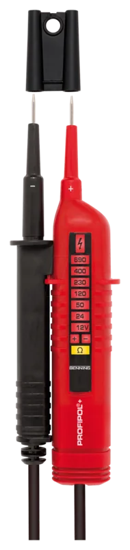
2. Device description (figure A)
1
Probe tip protector
2
Probe tip - (negative)
3
Probe tip + (positive)
4
Sensor of the cable break detector
5
Handle
6
Display handle
7
Battery compartment
8
Red LED ( for external conductor test (phase
indication)
9
LED step indicator
J
+/- LEDs of the polarity indication
K
Yellow LED Ω for continuity test/cable break
detector
3. Functional test (figure B)
- Check the voltage tester for correct functioning
immediately before and after using it!
- Short-circuit the probe tips
2
and
3
to check the

Chat with your Benning PROFIPOL+ manual using AI

Get instant AI answers from your Benning PROFIPOL+ manual

Ask anything about the Benning PROFIPOL+. Answers come from this manual, with the pages they are based on.

PROFIPOL+ Maintenance Schedule

Before and after each use
Perform functional test of the voltage tester

Check the device for correct functioning immediately before and after every use by shorting probe tips and testing on a known voltage source.

As needed / During cleaning
Clean housing and battery compartment

Clean the exterior of the device with a clean dry cloth. If contamination is present in the battery area, clean it with a dry cloth as well.

When storing long-term
Remove batteries from device

If the device is stored for a longer period of time, remove the batteries from the device to prevent damage or leakage.

M: qwen/qwen3.8-flash

Ask a Question

0/1000

Do you recommend PROFIPOL+?

Yes No
0
User Pic

W. S.

5 months ago

Is this product easy to install for someone without electrical experience?

0
User Pic

Manual.ly

5 months ago

Yes, the product is designed to be user-friendly and can be installed by individuals without professional electrical training. The instructions are clear, and many users have successfully completed the installation themselves.

M: QW-35-FL
M: QW-35-FL
0
User Pic

Tom Klein

6 months ago

How would you describe the build quality and handling of this item?

M: QW-35-FL

Frequently Asked Questions

A

The device is designed to test nominal voltages ranging from 12 V up to 690 V AC/DC. It is suitable for use in overvoltage categories CAT III up to 600 V and CAT II up to 690 V.

Is this answer helpful?

A

Before and after every use, you must perform a functional test by short-circuiting the probe tips. This should activate the buzzer and light up the yellow continuity LED. If these do not work, replace the batteries immediately.

Is this answer helpful?

A

Yes, you can perform two-pole voltage tests using the LED step indicator even with exhausted batteries. However, other functions like the buzzer and phase indication will not work without power.

Is this answer helpful?

A

The detector uses a sensor on the handle to locate breaks in live cables without contact. You run the sensor along the cable; the yellow LED stays lit until it reaches the break point where it turns off.

Is this answer helpful?

A

The tester requires two Micro batteries, specifically type LR03 or AAA (1.5 V). Ensure they are inserted with the correct polarity as indicated by the symbol inside the compartment.

Is this answer helpful?

A

No, the LED step indicator is designed to show the voltage range, not for precise measurement purposes. It indicates whether voltage is present and roughly how high it is within the specified limits.

Is this answer helpful?

M: QW-35-FL

Advantages and Disadvantages

Advantages

  • Comprehensive voltage detection range from 12 V to 690 V AC/DC
  • Non-contact cable break detector for safe localization of faults
  • Dual-pole and single-pole testing capabilities with clear LED indicators
  • Built-in functional self-test ensures reliability before every use
  • Robust IP54 protection against dust and water splashes
VS

Disadvantages

  • Maximum continuous operation time limited to 30 seconds per cycle
  • Impedance may cause interference voltage misreadings in some scenarios
  • Requires removal of batteries during long-term storage to prevent leakage
  • Single-pole phase test requires full hand coverage of handles for accuracy
  • Not intended for precise measurement but rather for range indication
M: QW-35-FL

Product Specification

Measurement range

12-690V

M: QW-35-FL

Product Description

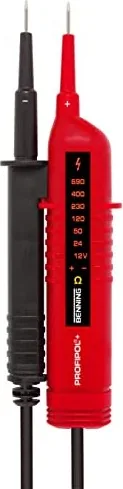
Benning Profipol Voltage Tester: Essential Safety for Electricians

The Benning Profipol Voltage Tester stands as a critical tool for any professional electrician or electrotechnically trained person. Designed to ensure safety during electrical work, this device offers comprehensive functionality for detecting voltage presence, verifying phase indicators, and locating cable breaks without direct contact. Whether working on residential circuits or industrial installations, the PROFIPOL+ provides reliable data through its intuitive LED display system.

This tester is engineered to handle nominal voltages ranging from 12 V up to AC/DC 690 V. Its robust construction meets strict international standards, including DIN EN 61243-3 and IEC 61243-3, ensuring it performs reliably in demanding environments. The device features dual probe tips for two-pole testing and a specialized sensor for non-contact cable break detection. Users can quickly distinguish between alternating current (AC) and direct current (DC) based on specific LED patterns, while the polarity indicator clarifies positive and negative connections.

Safety remains the paramount feature of the Benning Profipol Voltage Tester. The unit includes insulated handles that must be gripped fully to ensure capacitive coupling to earth during single-pole phase tests. A built-in functional test allows users to verify the buzzer and LEDs before every use, preventing dangerous false readings. The device automatically switches modes if voltage is detected during a continuity check, adding an extra layer of protection against accidental shock.

Maintenance is straightforward, requiring only a dry cloth for cleaning and periodic battery replacement using standard AAA cells. The IP54 rating ensures resistance against dust and water jets, making it suitable for various job site conditions. By adhering to the recommended duty cycle of 30 seconds, users can maximize the longevity and accuracy of this indispensable diagnostic instrument.

M: QW-35-FL

© Copyright 2026 Manual.ly
