
Benning IT 105 Manual
PDF manual · 79 Pages
English



Quick check
Incorrect answer, please try again.
Chat with your Benning IT 105 manual using AI
Get instant AI answers from your Benning IT 105 manual
Ask anything about the Benning IT 105. Answers come from this manual, with the pages they are based on.
IT 105 Maintenance Schedule
Send the device to the Benning service center annually to maintain specified accuracy.
Replace all six batteries immediately when the battery symbol flashes on the display.
Replace the internal fuse only if the defective fuse symbol appears or after overload.
Wipe the exterior with a clean dry cloth. Do not use solvents or abrasives.
Free maintenance reminders
Timed to your purchase date. Always free, unsubscribe anytime.
Ask a Question
Do you recommend IT 105?
Yes NoFrequently Asked Questions
The IT 105 measures voltage and frequency, phase sequence, insulation resistance (250/500/1000 V), low-resistance continuity (RLOW, 200 mA), loop/line impedance (ZS/ZI) in NO-TRIP and HIGH CURRENT modes, and RCD tripping time and trip current (RCDt, RCDI).
Is this answer helpful?
Yes. It supports automatic RCD tripping sequences (AUTO) and manual modes (½×, 1×, 5× IΔN) with selectable polarity and waveform (AC or pulsed Type A). The main display shows measured trip time and the unit monitors PE contact voltage, blocking tests if unsafe levels (>50 V) are detected.
Is this answer helpful?
Use the NO-TRIP mode which applies a low test current to usually avoid upstream RCD tripping. If residual fault currents exist the RCD can still trip; in that case retry or use measurement methods according to safety procedures.
Is this answer helpful?
The device is for dry environments (IP40) and operation between 0 °C and 40 °C, up to 2000 m elevation. Only qualified personnel should use it; observe CAT III limitations (max 300 V conductor to earth) and use supplied CAT-rated accessories for category III measurements.
Is this answer helpful?
It uses six AA (IEC LR6) batteries. The instrument indicates low battery on the display. Replace batteries when the battery symbol flashes. It contains a replaceable fuse (1.6 A, 1000 V FF). Regular cleaning and an annual factory calibration are recommended to maintain accuracy.
Is this answer helpful?
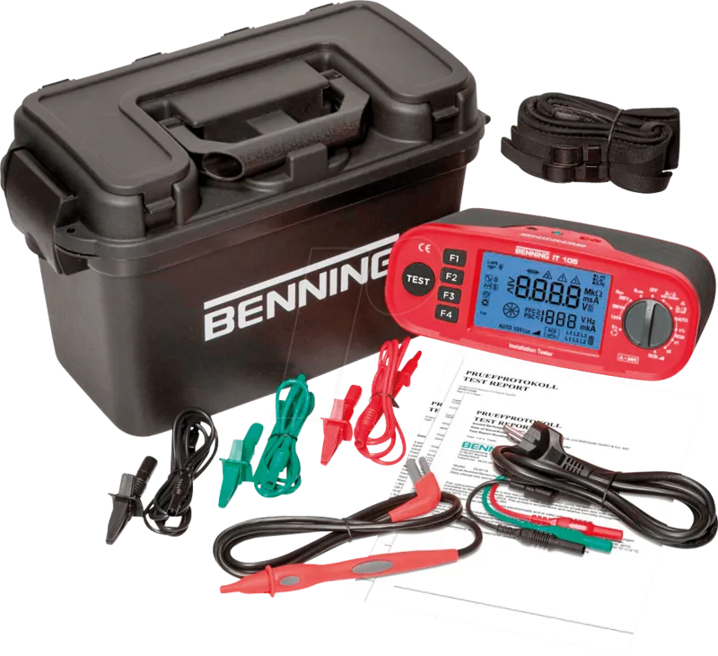
Included: tester, transport case, test probe with TEST key, test cable with shock-proof plug, measuring leads/alligator clips, 4 mm adapter, carrying strap, six AA batteries, fuse and calibration certificate. Optional: long measuring leads with reel (e.g., BENNING TA5 40 m) for protective conductor measurements.
Is this answer helpful?
Accuracy depends on function: voltage ±(5%+2 digits) up to 440 V; continuity RLOW ±(2%+5 digits); insulation RISO ±(5%+5 digits); loop/line impedance ZS/ZI ±(5%+5 digits) with finer resolution ranges; RCD times ±(5%+2 digits). Calibrate annually to keep specifications.
Is this answer helpful?
Advantages and Disadvantages
Advantages

- Comprehensive multifunction tester: voltage, RISO (250/500/1000 V), RLOW, ZS/ZI, RCDt/RCDI.
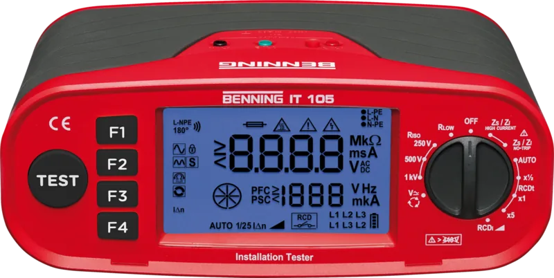
- Clear backlit display with function keys, LOCK/AUTO features and TEST probe for easy operation.
- Calculates prospective fault current (PFC) and short-circuit current (PSC) for protection assessment.
- Meets IEC/EN safety and EMC standards; includes overload fuse and PE contact-voltage monitoring.
- Supplied complete with leads, test cable, probe, 4 mm adapter, case, batteries and calibration certificate.
Disadvantages

- Not intended for wet environments (IP40) — limited water protection.
- High-current loop tests can trip upstream RCDs and require care during measurement.
- Battery-powered (six AA) — frequent field use requires spare batteries and periodic replacement.
- Fuse replacement and deeper repairs require qualified service; user-accessible repairs limited.
- Maximum safe measurement category limits (CAT III up to 300 V to earth) — observe limitations.
Product Description
BENNING IT 105 Installation Tester
The BENNING IT 105 is a compact, multifunctional installation tester designed for electrical safety verification in accordance with IEC 60364-6 and EN 50110. Built for field technicians and qualified personnel, the tester provides a wide range of measurements including voltage, frequency, phase sequence, insulation resistance (RISO) at selectable test voltages (250/500/1000 V), low-resistance continuity (RLOW) with 200 mA test current, RCD timing and trip-current tests (RCDt, RCDI), and loop/line impedance (ZS/ZI) measurements with both low (NO-TRIP) and high (HIGH CURRENT) test currents. It also calculates prospective fault current (PFC) and short-circuit current (PSC) for assessing protective device operation.
Key product details
The tester features a clear backlit digital display with main and sub-displays for measured values, progress and status icons, and dedicated function keys (F1–F4) plus a TEST key for direct operation. A rotary function selector selects measurement modes including V, RISO (three voltages), RLOW, ZS/ZI (HIGH CURRENT and NO-TRIP), and multiple RCD test modes (AUTO, x½, x1, x5, ramp). The device monitors mains connection and contact voltage on PE to protect users during RCD testing and indicates overheating, low battery, or blown fuse conditions.
Ergonomically packaged, the BENNING IT 105 is delivered with measuring leads (black/blue/green), a test cable with shock-proof plug, a probe with TEST key, alligator clips, a 4 mm adapter, carrying strap, six AA batteries, a fuse, transport case and calibration certificate. The unit is rated IP40 for dry-environment use, works up to 440 V measurement range, and is specified for use up to 2000 m altitude. It meets relevant EN/IEC safety and EMC standards and includes built-in protections such as an internal fuse and polarity/adaptation safeguards.
Applications and workflow
Typical uses include routine electrical installation verification, RCD commissioning and periodic testing, motor and three-phase loop and line impedance checks, insulation and continuity testing, and fault-current estimation for protective-device coordination. The device supports AUTO-start functions, LOCK for continuous insulation testing, null compensation for lead resistance, and selectable RCD test current and waveform (AC or pulsed Type A). Calibration is recommended annually to maintain specified measurement accuracy.
Notes
- Intended for qualified personnel only; follow all local electrical regulations.
- Use only included CAT-rated leads and accessories for CAT III measurements.
- Remove batteries for long-term storage and replace batteries/fuse as indicated by display symbols.
- High-current ZS/ZI tests can trip upstream RCDs; use NO-TRIP mode when required.
Search for 67,706 Manuals online


Type-in Brand or Model
Rosie Wood
8 months ago
Is this product solidly built, and does it come with good accessories?
Manual.ly
8 months ago
Customers describe the device as having solid, well-finished workmanship and note that the included accessories are good. For the exact scope, please compare the package contents listed on the product page, since accessory sets can vary by bundle and region.