
Benning DUTEST pro Manual
PDF manual · 52 Pages
English



Quick check
Incorrect answer, please try again.
Chat with your Benning DUTEST pro manual using AI
Get instant AI answers from your Benning DUTEST pro manual
Ask anything about the Benning DUTEST pro. Answers come from this manual, with the pages they are based on.
DUTEST pro Maintenance Schedule
Press the button for approx. 5 seconds to test all LEDs, torch, and buzzer. Short-circuit probes to verify internal circuit and batteries.
Replace batteries immediately if the continuity test LEDs flash during the functional check.
Wipe the outside of the device with a clean dry cloth to remove dirt or deposits.
Clean any contamination or deposits around the battery compartment with a dry cloth.
Take the batteries out of the device if it will not be used for an extended period.
Ask a Question
Do you recommend DUTEST pro?
Yes NoFrequently Asked Questions
It supports continuity tests, diode tests (including direction indication), external voltage detection for AC/DC with polarity, a single-pole phase check, and non-contact cable-break localization.
Is this answer helpful?
The external voltage indication covers 6 V to 400 V for both AC and DC (50/60 Hz). Red LEDs show whether the detected voltage is AC or DC and also provide polarity information.
Is this answer helpful?
No. The external-voltage indication warns about present voltage, but it does not replace a two-pole voltage tester to verify the absence of voltage before working.
Is this answer helpful?
Continuity uses a buzzer plus three yellow LED steps corresponding to resistance ranges (low ohms to higher ohms). Diode direction is identified by applying probe polarity so the yellow LEDs illuminate in the conducting state.
Is this answer helpful?
It locates cable breaks non-contact by scanning along an exposed live line from the feeding end toward the other end. While the line is unbroken, the red indicator flashes; when the break point is reached, the indicator goes out.
Is this answer helpful?
Yes. The torch has four brightness levels (25%, 50%, 75%, 100%). The buzzer volume can be set in multiple steps, including a setting that turns the buzzer off while keeping the torch on.
Is this answer helpful?
Advantages and Disadvantages
Advantages

- Continuity testing with buzzer plus three yellow LED ranges for low-resistance checks
- Diode testing with conducting-direction indication using probe polarity
- External voltage detection for AC and DC from 6 V to 400 V with polarity LEDs
- Single-pole phase test and non-contact cable break detection for practical troubleshooting
- Built-in high-power LED torch with four brightness levels and adjustable buzzer volume
Disadvantages

- External-voltage indication does not replace a two-pole voltage tester for proving voltage absence
- Continuity and diode testing require de-energized parts (and discharge of capacitors if needed)
- Continuity resistance result is rough (LED steps with tolerance around the max LED step value)
- Single-pole phase and cable break functions are intended for specific grounded mains conditions
- IP40 protection is limited; device must be kept dry and protected from condensation
Product Specification
Measurement Range
6-400V
Product Description
Benning Dutest Pro Voltage tester - Manual
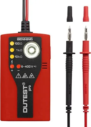
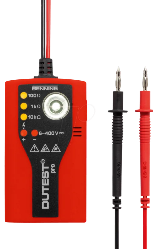
The Benning Dutest Pro Voltage tester is a rugged, electrician-focused tool designed for fast, visual and acoustic diagnostics during installation and maintenance. Using two insulated test probes, it helps you check continuity, test diodes, identify external voltage, determine polarity, perform a single-pole phase check, and locate cable breaks without direct contact. The Benning Dutest Pro Voltage tester Manual highlights how the device combines multiple functions into one compact tester, so field work moves quickly and confidently.
For continuity checks, the tester uses a three-step yellow LED scale plus a buzzer. Depending on the measured resistance range, different LED levels illuminate, giving a rough estimate of whether the connection is low-ohmic or likely open. It also supports diode testing and can indicate diode direction by switching probe polarity, with the yellow LEDs showing the conducting state.
Safety and awareness are core parts of the design. Red LEDs provide external voltage indication for both AC and DC in the 6 V to 400 V range (50/60 Hz). Polarity is displayed with the corresponding plus and minus LEDs. The device emphasizes that external-voltage indication does not replace a two-pole voltage tester for confirming the absence of voltage.
For phase work, the single-pole external conductor test (phase) indicates whether an AC phase is present, while an integrated cable-break detector can find local breaks along exposed live lines by tracking where the signal disappears. This makes the Benning Dutest Pro Voltage tester especially useful for troubleshooting lighting strings, cable reels, and other in-field circuits.
A built-in high-power LED torch adds convenience when working in dark panels or cramped spaces. You can switch it on and off and set brightness in four levels (25%, 50%, 75%, 100%). The buzzer volume is also adjustable across multiple steps, including a mode that turns the buzzer off while keeping the torch on.
Key results
- Continuity and diode testing with a buzzer plus a three-step LED scale for quick pass-or-warn decisions.
- AC/DC external voltage detection from 6 V to 400 V, with polarity indication via dedicated LEDs.
- Single-pole phase checking and a non-contact cable-break detector for faster troubleshooting.
- CAT III 300 V safety design plus an IP40 housing for protected everyday use.
Notes
- Continuity and diode tests must be performed on de-energized system parts; stop immediately if external voltage is detected.
- IP40 means avoid moisture, wet conditions, and condensation.
- Replace batteries when the continuity LEDs flash; keep the battery compartment closed during operation.
Search for 67,706 Manuals online


Type-in Brand or Model
Destiney Halvorson
10 months ago
Does this tester provide both optical and acoustic continuity signaling, and is it compact enough for regular electrician use?
Manual.ly
10 months ago
Yes. It is designed for many test applications and performs continuity (through-connection) checks with both visual (optical) and audible (acoustic) feedback. The signal is provided in stages, so you can quickly see and hear the result during line checks. Reviewers also describe it as small and handy for everyday use in the field, which makes it comfortable when working on cables. Note: one user mentioned the housing plastic feels less premium, but overall it is considered to do its job reliably.