Manual.ly Logo

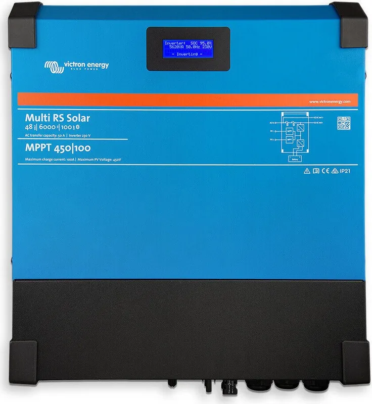
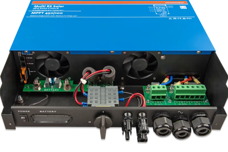
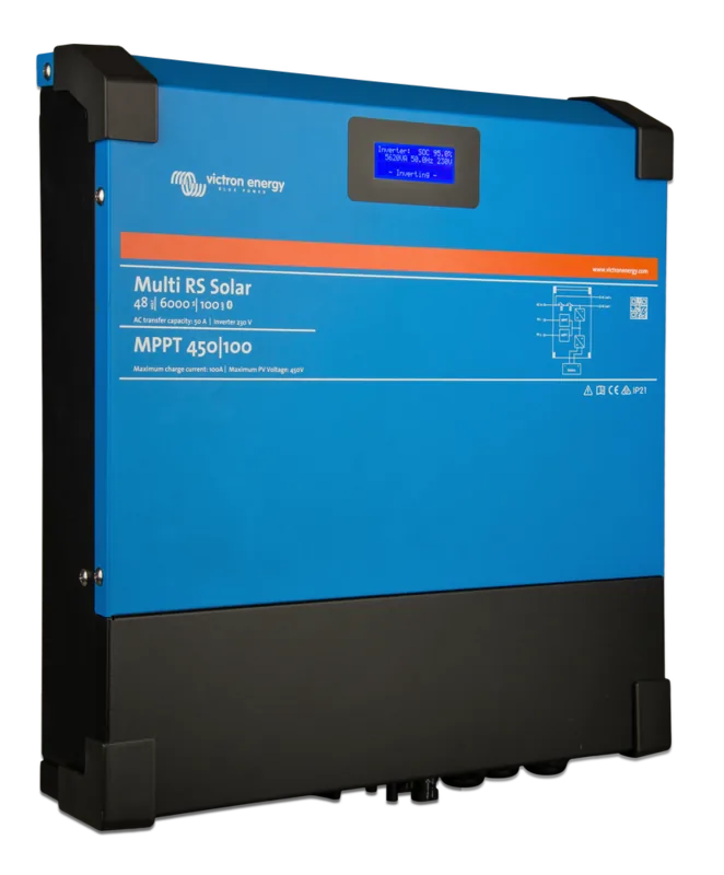
Victron Energy Multi RS Solar 48/6000/100-450/100 Manual

0.0 · 0 Ratings

PDF manual · 63 Pages

English

M: QW-35-FL
page

/ 63

Loading...
c8403556f184ccfbeadda53a5fe3df1dfa09 page 3e
Abbildung 6. Vollständiger Schaltplan von Multi RS Solar
victron energy
BLUE POWER
25.6V-200Ah
Lithium
Smart LiFePO4
victron energy
BLUE POWER
25.6V-200Ah
Lithium
Smart LiFePO4
victron energy
BLUE POWER
25.6V-200Ah
Lithium
Smart LiFePO4
With Power assist the Multi RS can add 6kVA
or 26A to AC Out-1 for peak handling when
needed. The Multi RS can throughput 50A from
the AC input directly to the output loads.
The AC input relays are limited to 50A max.
An Earth leakage device with a breaker size of
50A max or less or a combination MCB/RCD
must be installed on the output of AC Out-1.
Cable size should be adjusted accordingly.
Recommended AC Out-1 cable/breaker size Multi RS
AC Out-2 only is available when power is
present on AC IN and AC Out-2 supports up
to 50A similar to the maximum connected
AC IN power source as they are internally
connected. An Earth leakage device with a
breaker size of 50A max or less or a
combination MCB/RCD must be installed
on the output of AC Out-2. Cable size
should be adjusted accordingly.
Recommended AC Out-2 cable/breaker size Multi RS
When operating in inverter mode, the Neutral output of a
inverter/charger must be connected to ground to guarantee
proper functioning of a GFCI or RCD device. In case of a
split phase supply the Neutral also must be grounded.
In a fixed installation like in this drawing, an uninterruptible grounding
can be secured with the grounding wire of the AC input. It will however
be good practice to ground the casing to the AC ground Busbar in the
AC Distribution panel as well as is visible in this drawing.
IMPORTANT INFORMATION !
IMPORTANT INFORMATION ! IMPORTANT INFORMATION ! IMPORTANT INFORMATION ! IMPORTANT INFORMATION !
Recommended DC cable/fuse size Multi RS Solar Recommended AC IN
cable/breaker size Multi RS Solar
AC IN must be protected by a circuit
breaker rated at 50A max or less. This
depends heavily on the size of the
connected power source.The input current
must be adjusted to fit the size of the
connected power source.
The breaker and cable size for AC IN
should be adjusted accordingly.
0-2 m cable length: 35SQmm, 2-5 m cable length:
70SQmm. When used in closed conduits, cable
size should double. Cable length stands for the
distance between the batteries and the Multi RS
connections !!! Recommendations are without
other loads in the system and these also should be
taken into account for proper main battery, main
fuse & main switch cables !!!
Fuse size should be 125-150A.
4 x Lithium 25.6V-200Ah
Smart LiFePO4
60 Volt/16mA
CERBO GX
HDMI
VRM
WORLD
CERBO Power -
ETHERNET
CERBO Power +
GX TOUCH 50
victron energy
victron energy
InvertingAC Input AC Loads
0W 425W
+
victron energy
PV-Charger
1250W
-....W
DC Power
-
870W
51.2V 17A
75%
victron energy
BLUE POWER
25.6V-200Ah
Lithium
Smart LiFePO4
ANL
200A
ANL
200A
Battery Pre Main Fuses
Li-DISTRIBUTION
NEGATIVE BUSBAR
Cerbo 1A fuse
HOUSE
ON
OFF
F
F
O
O
T
G
N
I
H
C
T
I
W
S
E
R
O
F
E
B
E
N
I
G
N
E
P
O
T
S
I
G
N
I
T
I
O
N
P
R
O
T
E
C
T
E
D
e
v
o
m
e
R
150A
BF2|58V
smallBMS
Load ON
Temp or OVP
victron energy
BLUE POWER
Bat +
Bat -
Remote L
Remote H
Load
Pre-alarm
Charger
DIN END STOP
DIN END STOP
FUSE
5x20
FUSE
5x20
BMS 1A fuse
The smallBMS is enlarged visible
These BMS M8 circular connectors are enlarged visible
All BMS M8 Circular connectors are
daisy chained connected to the BMS !
BMS On/Off Switch
PRE-ALARM BUZZER
Multi RS
Main Fuse
Multi RS remote-L
Multi RS remote-H
from smallBMS
I/O-5 Remote-L
I/O-6 Remote-H
Din Rail
Terminal
fuses
VE.Can
VE.Direct
VE.Can
User I/O
1 2 3 4 5 6
789101112
Multi RS Solar 48/6000 Dual Tracker
PV2
power
VE.Can
VE.Can to/from Cerbo
To/From Cerbo
GX TOUCH 50
ATD or LOAD DISCONNECT-H/6
ATC or CHARGE DISCONNECT-L/5
From SmallBMS
VE.CAN to/from Cerbo
To/From Cerbo
VE.Can TERMINATOR
Multi RS Solar enlarged
I/O & Data connections
Single Circuit
MAIN SWITCH
Multi RS Solar Arrays
Bottom left hand side
1 Relay_NO
I/O Number Connection
2 AUX_IN-
3 AUX_IN1+
4 AUX_IN2+
5 REMOTE_L
6 REMOTE_H
7 RELAY_NC
8 RELAY_COM
9 TSENSE-
Description
10 TSENSE+
11 VSENSE-
12 VSENSE+
Programmable relay Normally Open connection
Common negative for programmable auxiliary inputs
Remote On/Off connector Low or ATC connection with SmallBMS
Remote On/Off connector High or ATD connection with SmallBMS
Programmable relay Common negative
Temperature Sensor negative
Temperature Sensor Positive
Programmable auxiliary input 1 positive connection
Programmable auxiliary input 2 positive connection
Programmable relay Normally Closed connection
Voltage Sensor negative
Voltage Sensor Positive
User I/O functions Multi RS and MPPT RS
location:
Optional MPPT RS Solar Array
BREAKER/ISOLATOR
1 2 3 4 5 6
789101112
User I/O
When using Victron lithium batteries, the system will need to be
wired using the allow to charge ATC, and allow to discharge ATD
contacts from the Victron smallBMS to the I/O connection port of
both RS devices. This will also need to be configured to BMS
mode when commissioning the product with VictronConnect.
Victron LiFePO4 Smart batteries
IMPORTANT INFORMATION !
KEEP NEGATIVE BATTERY CABLES ALL AS SHORT
AS POSSIBLE AND ALL AT THE SAME LENGTH !
KEEP POSITIVE BATTERY CABLES ALL AS SHORT
AS POSSIBLE AND ALL AT THE SAME LENGTH !
The Multi RS Solar has a built in AC PV inverter detection system. When feedback is
detected of AC PV power on the AC-output side, frequency shift will automatically be
enabled. While no further configuration is required, it is important that the AC PV inverter
is configured correctly to respond to a rising frequency adjustment by reducing its
output. Be aware of the 1:1 rule of any AC PV inverter size to the Multi RS size, and
minimum battery sizing applies. More information about these limitations are available in
the Victron AC Coupling manual, and this document is required reading if using any AC
PV inverter. More info is available in the Multi RS manual and on the website.
Solar array configuration setup info-3
IMPORTANT INFORMATION !
VE.Can to/from Multi RS
The Multi RS Solar Dual Tracker contains multiple
PV input connectors. These are wired to two
individual Maximum Power Point Trackers.
It is possible to use different panel configurations
within the specifications for each PV input
connector. You should NOT connect the same PV
array to both tracker inputs.The max operational
input current per PV input is 13A.
Solar array configuration setup info-1
IMPORTANT INFORMATION !
When the RS MPPT switches to float stage it reduces the battery charge current by
increasing the PV Power Point voltage. The maximum open circuit voltage of the PV
array must be less than 8 times the minimum battery voltage when at float.
For example, where a battery has a float voltage of 54.0 volts as with the batteries
used in this drawing, the maximum open circuit voltage of the connected array cannot
exceed 432 volts. Where the array voltage exceeds this parameter the system will give
a "Over-charge Protection" error and shuts down. To correct this, simply reduce the
PV voltage by removing a panel from the Array string.
Solar array configuration setup info-2
IMPORTANT INFORMATION !
150A
BF2|58V
Optional SmartSolar MPPT RS
I/O-5 Remote-L
I/O-6 Remote-H
VE.Can
IMPORTANT INFORMATION !
From terminal fuse
Multi RS remote-L/5
Multi RS remote-H/6
From central negative
MPPT remote-H/6
MPPT remote-L/5
POWER +
CHARGE DISCONNECT
PRE-ALARM +
ON/OFF SWITCH
LOAD DISCONNECT
POWER -
ON/OFF SWITCH
VE.Can to/from MPPT RS
MPPT RS remote-L
MPPT RS remote-H
from smallBMS
VE.Can to/from Cerbo
To/From Cerbo
FROM PV
PV
power
0 OFF
name
0 OFF
MCB
VE.Can
VE.Direct
VE.Can
User I/O
1 2 3 4 5 6
789101112
ATD or LOAD DISCONNECT-H/6
ATC or CHARGE DISCONNECT-L/5
From SmallBMS
VE.CAN to/from Cerbo
To/From Cerbo
VE.Can TERMINATOR
MPPT RS Solar enlarged
I/O & Data connections
Bottom left hand side
location:
0 OFF
name
0 OFF
MCB
PV1
power
PV-1 Power +
PV-1 Power -
PV-2 Power +
PV-2 Power -
0 OFF
name
0 OFF
MCB
WARNING !
High Voltage DC
WARNING !
High Voltage DC
PV
BREAKER
ISOLATOR
BJE-303B
WARNING !
230V Volt AC
GRID Power
WARNING !
230V Volt AC
AC Power from Grid
Output-1
AC Power from:
Multi RS
AC Out-1
Multi RS
AC Out-2
0 OFF
:hager
0 OFF
:hager
0 OFF
:hager
0 OFF
:hager
0 OFF
:hager
0 OFF
:hager
MCB/RCD MCB/RCD
Output-2
AC Power from:
0 OFF
name
0 OFF
MCB
AC in
name
ADxxxxx
xxA/I n0.03A
test regularly
0
earth fault indicator
1 N
2 N
T
Bx
name
ADxxxxx
xxA/I n0.03A
test regularly
0
earth fault indicator
1 N
2 N
T
Bx
No Break load-3
No Break load-2
No Break load-1
Switched load-3
Switched load-2
Switched load-1
Multi RS AC OUT-2
Multi RS AC OUT-1
Multi RS AC IN
smallBMS-
CERBO-
MPPT RS remote-H/6
MPPT RS remote-L/5
VE.Can to/from MPPT RS
MPPT RS remote-H/6
MPPT RS remote-L/5
Be aware that local rules
may require alternative
AC ground configurations !
IMPORTANT INFORMATION !
Die höchste Auflösung und die aktuellsten Schaltpläne finden Sie unter https://www.victronenergy.de/inverters-chargers/multi-rs-
solar#system-schematic
Multi RS Solar
Seite 59 Anhang

Chat with your Victron Energy Multi RS Solar 48/6000/100-450/100 manual using AI

Get instant AI answers from your Victron Energy Multi RS Solar 48/6000/100-450/100 manual

Ask anything about the Victron Energy Multi RS Solar 48/6000/100-450/100. Answers come from this manual, with the pages they are based on.

Ask a Question

0/1000

Do you recommend Multi RS Solar 48/6000/100-450/100?

Yes No

Frequently Asked Questions

A

Yes, it supports Lithium batteries with proper BMS communication configuration via VictronConnect settings.

Is this answer helpful?

A

The total maximum solar power input is 6000 watts split between two independent trackers.

Is this answer helpful?

A

Yes, you can connect generators using firmware version v1.11 or higher for optimal performance.

Is this answer helpful?

A

Yes, 3-phase operation is possible using three individual units synchronized via VE.CAN network.

Is this answer helpful?

A

You can monitor remotely via the VictronConnect app or connect to the VRM portal online.

Is this answer helpful?

A

The system shuts down temporarily to protect components then restarts automatically when stable.

Is this answer helpful?

A

Yes, it has a four-line backlit LCD display showing system data and battery status.

Is this answer helpful?

M: QW-35-FL

Advantages and Disadvantages

Advantages

  • High conversion efficiency ensures minimal energy loss during daily operational cycles.
  • Dual AC outputs allow separation of critical loads from general household needs.
  • Integrated MPPT chargers optimize solar panel performance effectively.
  • VictronConnect software enables easy remote monitoring and configuration.
  • Robust safety features protect against overloads and overheating issues.
VS

Disadvantages

  • Limited support for complex Energy Storage System protocols initially.
  • Cannot synchronize multiple units for increased total power output yet.
  • AC input relays have fixed limits restricting certain grid configurations.
  • Requires specific firmware versions for generator input functionality.
  • Some programming features depend on external gateway devices for expansion.
M: QW-35-FL

Product Specification

Note

Prices include partial 0% VAT rates for AT and DE

Type

Hybrid Inverter, with Fan

Input Voltage

80-450V DC Voltage

Max Input Current

13A

MPP Voltage Range

80-450V DC Voltage

MPP Tracker Count

1

Max PV Generator Power

6kWp

Output Power

4.8kW

Output Phases

3-phase

Efficiency

94.0% max

Input Connector

MC4

Output Terminal

Terminals

Interfaces

Bluetooth

IP Rating

IP21

Ambient Temperature

-40°F to +149°F

Dimensions

17.32x16.73x4.92 inches (WxHxD)

Weight

27.12 lbs

M: QW-35-FL

Product Description

Victron Energy Multi RS Solar Overview

The Victron Energy Multi RS Solar 48/6000/100-450/100 VE.Direct represents a powerful hybrid solution for modern energy systems. Designed specifically for 48-volt battery banks, this unit combines a high-performance inverter and charger with a dedicated MPPT solar charge controller. Users benefit from a seamless integration that maximizes renewable energy harvesting while providing reliable backup power during grid outages. This equipment is engineered to withstand harsh conditions while maintaining high electrical efficiency up to 96 percent.

Key Features and Performance

With a continuous AC output of 6000 watts and a peak capacity reaching 9000 watts, this device handles significant loads including motor startups efficiently. The built-in PowerAssist function intelligently supplements load requirements using battery power when grid input is insufficient. Additionally, the PowerControl feature optimizes limited AC input currents to prevent overload while ensuring batteries remain charged. The integrated MPPT solar charger supports up to 6000 watts of solar input across two tracking channels, optimizing energy harvest even under partial shading conditions. Each tracker manages its own array independently to prevent mismatch losses and maximize overall system yield.

Connectivity and Control

Managing this system is straightforward through the VictronConnect application. Whether via Bluetooth, USB, or network connections using VE.Direct and VE.Can ports, users can monitor performance metrics in real time. The included LCD display provides immediate feedback on battery status, solar yield, and system health. Advanced programmability allows for customization of relay functions, remote on/off switching, and specific charging profiles tailored for lead-acid or lithium-ion batteries. You can connect temperature sensors to adjust charging voltages automatically based on ambient conditions for better longevity.

Installation and Limitations

Proper installation requires careful consideration of cabling sizes and ventilation spaces to prevent overheating. The unit must be mounted vertically to ensure adequate airflow and cooling protection is maintained throughout operation. While versatile, it does not currently support full Energy Storage System protocols or parallel configurations for increased power output beyond the rated unit specifications. Users wishing to expand capacity must manage separate units individually unless future firmware updates enable synchronization capabilities. Despite these constraints, the device excels in standalone solar applications where reliability is paramount. Always verify local electrical codes before connecting to public grids or sensitive medical equipment to ensure compliance and safety standards are met.

M: QW-35-FL

© Copyright 2026 Manual.ly