
ST7735R 1.8 inch TFT Display Module Manual
PDF manual · 164 Pages
English


Quick check
Incorrect answer, please try again.
Chat with your ST7735R 1.8 inch TFT Display Module manual using AI
Get instant AI answers from your ST7735R 1.8 inch TFT Display Module manual
Ask anything about the ST7735R 1.8 inch TFT Display Module. Answers come from this manual, with the pages they are based on.
Ask a Question
Do you recommend 1.8 inch TFT Display Module?
Yes No
Julia Schmidt
6 months ago
Is the documentation sufficient for connecting the SD card module to read BMP files?
Frequently Asked Questions
The ST7735R supports a maximum resolution of 132 pixels horizontally and 162 pixels vertically when using the GM[1:0]=00 setting. It can also operate at 128x160 pixels if configured differently.
Is this answer helpful?
Yes, the chip supports both 3-line and 4-line serial interfaces, allowing it to communicate easily with microcontrollers using standard SPI protocols for compact designs.
Is this answer helpful?
It can display up to 262,144 colors (262K) using 18-bit color depth. It also supports lower color depths like 16-bit (65K) and 12-bit (4K) for reduced bandwidth usage.
Is this answer helpful?
The RESX pin is used to reset the device. It must be applied properly to initialize the chip and clear any previous state before sending new commands.
Is this answer helpful?
Yes, the interface operation voltage (VDDI) ranges from 1.65V to 3.7V, making it fully compatible with standard 3.3V logic systems.
Is this answer helpful?
Exceeding the absolute maximum ratings may degrade product quality or cause physical damage. Always operate within the recommended voltage and temperature ranges.
Is this answer helpful?
You can enable the Tearing Effect Output by sending the TEON command to the driver. This signal synchronizes the MCU with the panel scan to prevent visual tearing.
Is this answer helpful?
Advantages and Disadvantages
Advantages

- Integrated 132x162x18 bit frame memory reduces external component count
- Supports multiple interface modes including SPI and 8/16/18-bit parallel
- Wide operating voltage range from 1.65V to 4.8V for flexibility
- Built-in DC/DC converter and oscillator simplify circuit design
- Programmable color depth allows optimization for different display needs
Disadvantages

- Maximum resolution limited to 132x162 pixels which may be low for some apps
- Requires careful power sequencing during startup to ensure stability
- Test pins must be configured correctly to avoid interference
- Complex timing requirements for parallel interfaces compared to serial
- Limited to specific refresh rates depending on interface selection
Product Specification
Manufacturer
Adafruit, SainSmart
Platform
Arduino
Diagonal
1.8" (4.57cm)
Resolution
160x120, 18bit
Contrast
1:400
Panel
JD-T18003-T01
Driver
ST7735R
Interface
SPI
External Connections
N/A
MCU
N/A
Power Supply
via Host
Touchscreen
N/A
Dimensions (WxDxH)
1.34x0.10x1.80in
Features
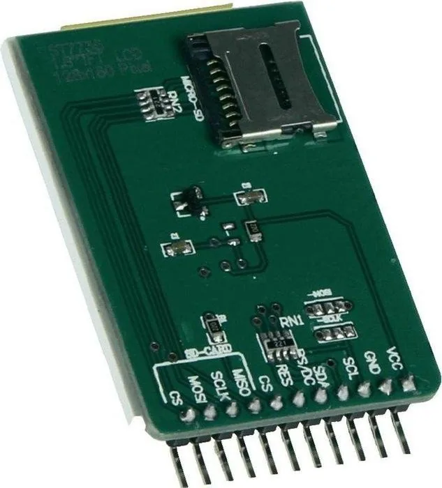
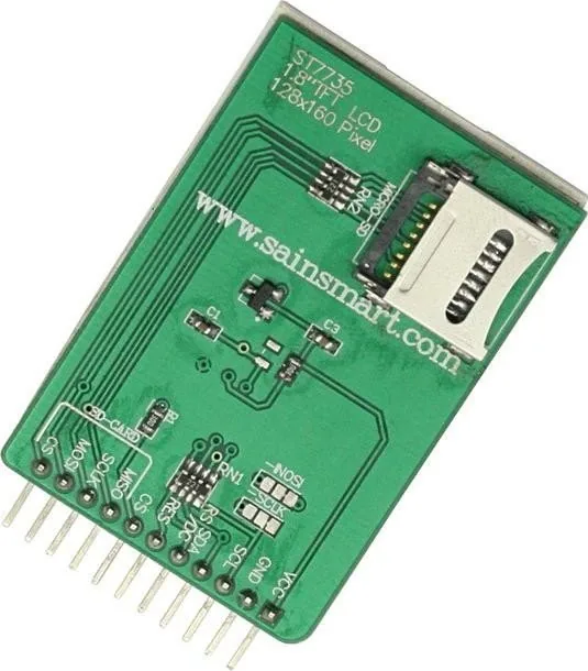
Embedded device, breadboard compatible, card reader (microSD)
Product Description
ST7735R Display Module 1.8 Inch MicroSD Manual Overview
The ST7735R is a highly efficient single-chip controller designed specifically for driving 262K-color graphic TFT-LCD displays. This versatile driver integrates 396 source lines and 162 gate line driving circuits, making it ideal for compact 1.8-inch screen applications often paired with microSD storage solutions for data logging or image playback. The chip supports direct connection to external microprocessors through multiple interface options including SPI, 8-bit, 9-bit, 16-bit, and 18-bit parallel interfaces. Its built-in display data RAM of 132 x 162 x 18 bits allows for on-chip frame memory operations without requiring an external clock, significantly reducing power consumption during idle states.
One of the standout features of this module is its flexible color depth support. Users can program the pixel color format to match their specific needs, choosing between 12-bit, 16-bit, or 18-bit per pixel modes. This adaptability ensures that the display can render everything from simple 4k color palettes to full 262k color graphics depending on the system requirements. The integrated power supply circuits eliminate the need for many external components, simplifying the overall design of the display system. Additionally, the chip includes a DC/DC converter, adjustable VCOM generation, and non-volatile memory to store initial register settings, ensuring reliable startup behavior every time the device powers on.
The module offers robust timing control and synchronization capabilities via a Tearing Effect output pin. This feature helps synchronize the microcontroller with the panel scan rate, preventing visual artifacts like tearing during video playback or rapid image updates. The wide supply voltage range accommodates various power environments, accepting logic voltages from 1.65V to 3.7V and analog voltages up to 4.8V. Whether you are building a portable media player, a custom instrument panel, or an embedded IoT device, the ST7735R provides the necessary hardware foundation for high-quality visual output.
Key Notes
- Supports both normal-black and normal-white LCD types.
- Includes factory default values stored in non-volatile memory for quick initialization.
- Compatible with standard SPI communication protocols for easy integration.
- Capable of partial display updates to save processing power and bandwidth.
Search for 67,706 Manuals online


Type-in Brand or Model
Graham Thompson
6 months ago
Does this display work with Arduino and ESP32, or do I need advanced Linux skills?
Manual.ly
6 months ago
This display is fully compatible with both Arduino and ESP32 platforms. Users have successfully operated it with libraries such as TFT_eSPI on ESP32 DevkitC V4 and the Adafruit_ST7735 library on Arduino. For optimal results with Arduino, ensure you initialize the display using tft.initR() rather than relying on default settings to avoid border artifacts. While some users experienced issues with outdated documentation suggesting older libraries, current examples are widely available online. Advanced Linux kernel compilation is not required for standard microcontroller use; however, if integrating with a Raspberry Pi running Linux, specific kernel configuration steps may be necessary.