
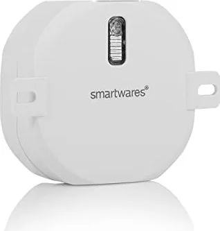
Smartwares SH4-90259 Manual
PDF manual · 4 Pages
English



Quick check
Incorrect answer, please try again.
Chat with your Smartwares SH4-90259 manual using AI
Get instant AI answers from your Smartwares SH4-90259 manual
Ask anything about the Smartwares SH4-90259. Answers come from this manual, with the pages they are based on.
Ask a Question
Do you recommend SH4-90259?
Yes NoFrequently Asked Questions
The receiver is designed for AC input at 220–240 V (nominal 230 V) and 50/60 Hz. Always isolate the circuit at the breaker before installation and verify local mains specifications.
Is this answer helpful?
Press and hold the receiver button for 3 seconds, release to enter pairing mode (LED blinks), then press the transmitter PAIR button for 2 seconds. The receiver LED lights and the transmitter LED blinks rapidly to confirm pairing.
Is this answer helpful?
There are four modes: A (manual up/down), B (close after 1 second — useful for garage doors/gates), C (close after 5 seconds — door openers), and D (close after 120 seconds — lighting). Cycle modes with transmitter I/ON and O/OFF and save your choice by holding the learning button for 3 seconds.
Is this answer helpful?
With the unit powered, press and hold the built-in switch button for 6 seconds, then follow the LED sequence: rapid blinking for 12 seconds, press again to slow blink, then steady LED. This clears all stored pairings.
Is this answer helpful?
Connect phase (brown) to L and neutral (blue) to N. Motor UP/OPEN pin connects to B, DOWN/CLOSE to A. If required, connect the motor phase (black) to C. Always consult the motor manual for correct potential-free contact wiring.
Is this answer helpful?
Maximum rated load is 300 W and the typical RF range is up to about 50 meters in open conditions; actual range may vary with obstacles and building structure.
Is this answer helpful?
Yes. The operating temperature range is 0–35°C. The device is intended for indoor or protected installations and should not be used in extreme temperatures or exposed outdoor conditions without adequate protection.
Is this answer helpful?
Advantages and Disadvantages
Advantages

- Easy retrofit into existing up/down switch positions for wireless control.
- Pairs with up to eight transmitters for multi-user or multi-control setups.
- Four programmable modes adapt to shutters, garage doors, door openers and lighting.
- LED feedback simplifies pairing, programming and reset procedures.
- Compact 230 V design fits typical domestic electrical installations.
Disadvantages

- 300 W maximum power restricts compatibility with higher-power motors.
- Around 50 m nominal range may be limited in complex or dense structures.
- Requires correct wiring and consultation of motor manuals for safe connections.
- No power backup — wireless control unavailable during mains outages.
- Operating temperature 0–35°C unsuitable for extreme or outdoor conditions.
Product Specification
Type
Actuator
Standard
Wireless Bus (434MHz)
Function
Switch Actuator (on/off)
Topology
Bus
Product Description
Smartwares SH4-90259 built-in wireless switch, switching actuator Manual
The Smartwares SH4-90259 built-in wireless switch is a compact switching actuator designed for replacing standard up/down wall switches and adding wireless control to roller shutters, garage doors, gates, door openers and lighting. It installs directly into the switch cavity and connects to the mains (L brown, N blue) and to motor control pins (A, B, C) following the motor manufacturer’s wiring. The unit operates at 230 V AC, supports 433.92 MHz transmitters, and stores up to eight paired senders. Typical range is about 50 m and maximum load around 300 W, making it suitable for many domestic motor-driven installations within its power rating.
Key features and operation
Pairing is simple: press and hold the receiver button for three seconds to enter pairing mode, then press the transmitter PAIR button for two seconds. LED feedback guides pairing and programming. The receiver supports four timer modes (A–D) that control automatic shut-off after predefined times to adapt use for shutters, garage doors, door openers or lighting. Mode selection is done via short and long presses on the receiver and using the transmitter I/ON and O/OFF buttons to cycle modes; save a mode by pressing the learning button for three seconds.
Installation requires powering down the circuit breaker, wiring phase and neutral to L and N, connecting motor UP/OPEN to B and DOWN/CLOSE to A (with motor phase to C where applicable), then mounting in the switch location. The product includes instructions for safe mounting and emphasizes consulting motor manuals for potential-free contact connections.
Practical use and maintenance
Once installed, basic control is via the paired transmitter: I/ON activates movement, O/OFF stops it. The receiver can be paired with multiple transmitters (up to eight memories). To clear all pairings, press and hold the built-in switch button for six seconds, follow the LED sequence and confirm to erase all stored links. Operating temperature is specified for typical indoor environments (0–35°C). The manual also stresses safety: turn off power at the breaker before wiring and follow the motor’s wiring instructions.
Notes:
- Supports four programmable modes for manual operation or timed close functions suited to shutters, gates, garage doors and lighting.
- LED behavior indicates pairing, programming windows and reset progress; program mode times out after 10 seconds if no signal is received.
- Not suitable for loads exceeding the specified maximum power; always check motor/manual compatibility.
Pros and Cons
Pros:
- Easy retrofitting into existing up/down switch locations.
- Wireless pairing with up to eight transmitters for flexible control.
- Four programmable modes for shutters, doors, gates and lighting.
- Clear LED feedback for pairing, programming and reset operations.
- Compact unit operating at standard 230 V AC for home installations.
Cons:
- Maximum power 300 W limits use with high-power motors.
- Range (~50 m) may be insufficient in complex building layouts.
- Requires correct wiring and motor compatibility knowledge.
- No battery backup; power loss disables wireless control.
- Operating temperature limited to 0–35°C, not for harsh environments.
Most important results
- Installation: Replace existing up/down switch, wire L (brown) and N (blue), connect motor pins A/B and motor phase to C; switch off breaker first.
- Pairing: Hold receiver button 3s, release, then press transmitter PAIR 2s; LED guides successful pairing; up to 8 transmitters.
- Modes: Four modes (A–D) control auto-off times (manual, 1s, 5s, 120s) for shutters, garage doors, door openers and lighting.
- Reset: Hold built-in switch 6s, follow LED sequence to clear all paired transmitters and memory.
- Specifications: 230 V AC, 50/60 Hz, max power 300 W, max range 50 m, RF 433.92 MHz, operating temp 0–35°C.
Search for 67,706 Manuals online


Type-in Brand or Model