
PeakTech 3705 Manual
PDF manual · 52 Pages
English



Quick check
Incorrect answer, please try again.
Chat with your PeakTech 3705 manual using AI
Get instant AI answers from your PeakTech 3705 manual
Ask anything about the PeakTech 3705. Answers come from this manual, with the pages they are based on.
3705 Maintenance Schedule
We recommend to calibrate the unit again after 1 year.
Replace the battery as soon as the BAT indicator appears on the display.
Wipe the cabinet regularly with a damp cloth and mild detergent. Do not use abrasives or solvents.
Free maintenance reminders
Timed to your purchase date. Always free, unsubscribe anytime.
Ask a Question
Do you recommend 3705?
Yes NoFrequently Asked Questions
Set the switch to the desired capacitance range. Insert the component into the test sockets matching polarity. If measuring low values, use the zero-adjustment feature. Ensure the capacitor is discharged before testing to avoid damage and error.
Is this answer helpful?
A battery symbol will appear on the screen. This indicates the voltage is dropping. Replace it immediately with a new 9V battery to prevent inaccurate readings or device malfunction.
Is this answer helpful?
Yes. Set the switch to the hFE position. Insert the transistor into the dedicated jack according to its NPN or PNP type. The display will show the approximate gain value.
Is this answer helpful?
It is rated for safety category II with an internal fuse for protection. However, never connect external voltage sources to the input terminals. Do not use it for high voltage applications outside its specifications.
Is this answer helpful?
Remove the battery and open the casing using a screwdriver. Locate the fuse holder and replace the 0.315A / 250V fuse with one of the exact same rating. Do not short the holder.
Is this answer helpful?
Remove the battery from the compartment. Store the unit in a dry environment between negative twenty and fifty degrees Celsius. Avoid exposure to direct sunlight and magnetic fields.
Is this answer helpful?
Advantages and Disadvantages
Advantages

- Provides comprehensive testing for capacitance, resistance, diodes, and transistors in one unit
- High accuracy with specific test frequencies allowing optimized measurements for capacitor types
- Built-in safety features including overload fuse protection to prevent damage from short circuits
- Clear 3.5-digit LCD display with automatic polarity indication and overrange warning
- Includes audible continuity buzzer for quick and easy circuit check troubleshooting
Disadvantages

- Requires manual range selection for each measurement type instead of automatic ranging
- Accuracy decreases significantly on the highest resistance ranges exceeding hundreds of megaohms
- Must be used strictly indoors and cannot withstand exposure to moisture or damp conditions
- Testing leads resistance can negatively impact accuracy for very small resistance values
- Battery must be disconnected before long-term storage to prevent leakage damage
Product Specification
Measurement Range
max. 2,000 MΩ
Product Description
Comprehensive Overview of the PeakTech 3705 LCR Meter
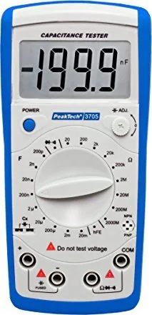
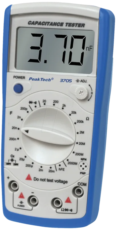
The PeakTech 3705 LCR Meter serves as a sophisticated tool for analyzing electronic circuit components. Professionals and enthusiasts value this device for its reliability and comprehensive measurement capabilities. Referencing the PeakTech 3705 LCR Meter Manual ensures that all operational limits are respected during usage. This instrument handles a variety of tasks ranging from basic resistance checks to complex capacitance verification.
Precision Capacitance Testing
One of the primary features is the wide capacitance measurement range. It supports values starting from picofarads up to millifarads with high resolution. Several test frequencies are available to optimize accuracy for specific capacitor types. The accuracy specifications remain tight across different ranges, typically within 0.5 percent plus ten digits for lower values. Users must ensure capacitors are fully discharged before inserting them into the test sockets to prevent damage. The device includes a zero-adjustment feature to compensate for lead resistance.
Resistance and Diode Analysis
The unit also measures resistance values from tens of ohms to thousands of megaohms. Overload protection is built-in using a fast-acting fuse rated at 0.315 amps. Diode testing allows for the assessment of forward voltage drops. A continuity check function provides an audible signal when resistance is low, facilitating quick troubleshooting of broken wires or solder joints. It is critical to connect the test leads to the correct ports to avoid erroneous readings or device failure.
Safety and Operational Constraints
Safe operation requires adherence to specific guidelines. The device is intended for indoor use only in clean environments. It must not be exposed to moisture or extreme heat. Battery life is monitored via an on-screen symbol that warns of low power. Low voltage can result in inaccurate data. Always remove the battery if the unit will not be used for an extended period. The casing should be wiped regularly with a soft cloth. Do not disassemble the unit unless you are a qualified technician.
Maintenance and Specifications
Regular maintenance keeps the meter in optimal condition. The 3.5-digit LCD screen is easy to read under various lighting conditions. The unit runs on a standard 9V block battery. Physical dimensions allow for easy storage in a toolkit. The battery compartment is secured with a screw to prevent accidental opening during transport. Calibration is recommended annually to maintain specification compliance. Ensure no external voltage sources are connected to the input terminals during any measurement process. Transistor testing is supported for hFE evaluation, making this a complete diagnostic solution for general electronics work in controlled environments.
Search for 67,706 Manuals online


Type-in Brand or Model