
Lian Li Uni Fan SL120 V2 Manual
PDF manual · 2 Pages
English



Quick check
Incorrect answer, please try again.
Chat with your Lian Li Uni Fan SL120 V2 manual using AI
Get instant AI answers from your Lian Li Uni Fan SL120 V2 manual
Ask anything about the Lian Li Uni Fan SL120 V2. Answers come from this manual, with the pages they are based on.
Ask a Question
Do you recommend Uni Fan SL120 V2?
Yes NoFrequently Asked Questions
You must connect to the PWM fan header and the 5 V ARGB 3 pin header specifically. Using any other voltage type can cause damage.
Is this answer helpful?
No, never connect to a 12 V connector. Doing so can cause permanent damage to the lighting system or power module.
Is this answer helpful?
Use the included M5x10 screws and do not use gaskets. Other screws may not hold the fan properly.
Is this answer helpful?
It measures 28 mm in thickness. It utilizes counterbore screw holes for compatibility with standard long screws.
Is this answer helpful?
Yes, but the interlocking key might interfere with ports. Fortunately, this specific key is removable to resolve spacing conflicts.
Is this answer helpful?
Available models include SL120 and SL140 sizes in Black or White color options like UF-SL120V2-1B.
Is this answer helpful?
Yes, fan to fan connection cables are included in the package to allow daisy chaining devices efficiently.
Is this answer helpful?
Advantages and Disadvantages
Advantages

- Directional connector design prevents incorrect power cable connections.
- Pulling connector mechanism effectively resists loosening from vibrations.
- Removable interlocking key allows installation on specific radiator layouts.
- Counterbore screw holes fit standard long screws easily without gaskets.
- Includes specific M5x10 screws for secure mounting stability.
Disadvantages

- Risk of permanent damage if connected to 12 V connector by mistake.
- Requires specific M5x10 screws as other screws may not hold properly.
- 28 mm thickness may interfere with smaller case configurations sometimes.
- Instructions require bilingual understanding for complete installation clarity.
- Removable key adds extra step during radiator mounting process.
Product Specification
Fan Connector
4-Pin PWM + 3-Pin ARGB (+5V / DATA / GND), Detachable cable
Dimensions
4.72x4.72x1.10 inches (WxHxD), 4.72-inch Fan
Fan Speed
250-2000 RPM
Fan Bearing
Fluid Dynamic Bearing (FDB)
Voltage Range
5-12V
Power Consumption
2.04W
Lighting
RGB
Manufacturer Warranty
2 Years
Product Description
Upgrading Your Cooling Setup
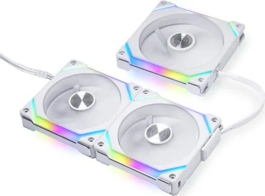
The Lian Li Uni Fan SL120V2 RGB Manual provides essential insights into modern chassis cooling solutions. Installing these fans requires precision significantly for safety and performance. Power cable installation requires attention to directional modular sockets. You must connect male-female plugs while ensuring pins remain covered by the plate. This design prevents accidental disconnection during operation. The pulling connector mechanism features a specific latch system designed to resist loosening from vibrations common in high-performance builds. Each package typically contains one PC unit of the fan along with four screws for secure attachment during assembly.
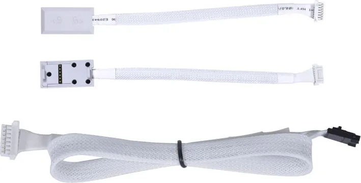
Note that connecting the power module to the motherboard involves critical steps regarding voltage specifications. You must connect to the PWM fan header and the 5 V ARGB 3 pin header specifically. Never connect to a 12 V connector. Doing so can cause permanent damage to the lighting system or power module. Safety protocols are emphasized to protect your expensive components. Fan to fan connection cables are included within the packaging to daisy chain devices efficiently for synchronized lighting effects. This ensures a seamless visual experience across your entire system layout.
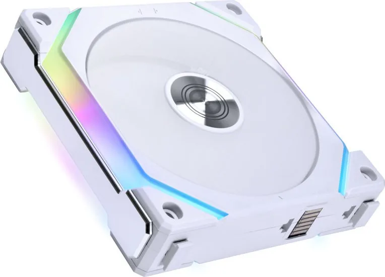
The fan thickness measures 28 mm, utilizing counterbore screw holes for compatibility with standard long screws. However, using gaskets along with long screws is discouraged because it compromises the intended fit. Only use the included M5x10 screws provided in the box to ensure fans remain secure. This is crucial for maintaining structural integrity within your case. When mounting fans on radiators, the interlocking key might interfere with inlet or outlet ports. Fortunately, this specific key is removable to resolve spacing conflicts without compromising the frame stability.
Available variants include UF-SL120V2-1B and UF-SL120V2-1W for twelve centimeter frames. Larger fourteen centimeter options exist as UF-SL140V2-1B or UF-SL140V2-1W. Understanding these specifications ensures optimal airflow and thermal management for your specific hardware needs. Proper assembly guarantees longevity and prevents hardware failure due to improper electrical connections. Enthusiasts should review these specifications before beginning any build process to avoid costly mistakes and ensure maximum performance from your cooling rig. Notes on maintenance suggest keeping dust away from the blades. Cleaning should be gentle to prevent bearing damage over time. Users often appreciate the anti-vibration pads included to reduce noise levels. It is recommended to double check all wiring diagrams before powering on the system to prevent any unexpected issues during initial startup. Following the provided guidelines helps maintain warranty coverage and ensures the product functions as designed by the manufacturer for years to come.
Search for 67,706 Manuals online


Type-in Brand or Model