3Hager 6LE002692B - 09/2020Hager Controls S.A.S., 33 rue Saint-Nicolas, B.P. 10140, 67703 SAVERNE CEDEX, France - www.hager.com
Safety instructions
Electrical equipment may only be installed and
assembled by a qualified electrician in accord-
ance with the relevant installation standards,
guidelines, regulations, directives, safety and
accident prevention regulations of the country.
Failure to comply with these installation in-
structions may result in damage to the device,
fire or other hazards.
Hazard due to electric shock. Disconnect be-
fore working on the device or load. Take into
account all circuit breakers that supply danger-
ous voltages to the device or load.
Hazard due to electric shock. The device is not
suited for safe disconnection of the mains sup-
ply.
Hazard due to electric shock on the SELV/PELV
installation. Not suitable for switching SELV/
PELV voltages.
Connect one motor per output only. If several
motors are connected, motors or device might
be destroyed.
Use drives with mechanical or electrical final
position switches only. Check final position
switches for correct adjustment. Observe mo-
tor manufacturer's data. The device could get
damaged.
Do not connect any three-phase motors. The
device could get damaged.
Observe the motor manufacturer's data regard-
ing change-over time and max. switch-on time
(ED).
These instructions are an integral component
of the product and must be retained by the end
user.
Design and layout of the device
30V DC
-
+
auto
C6
C5
C8C8
C7C7
9
11
C5C6
13
C7
15
C8
10
12
1416
C5C6C7C8
3
5
C2C3
7
C4
4
6
8
C2C3C4
C2C2
C1C1
C4C4
C3C3
1
N
L
C1
2
C1
(1)
(2)
(3)
(4)
(5)
(6)
(7)
(8)
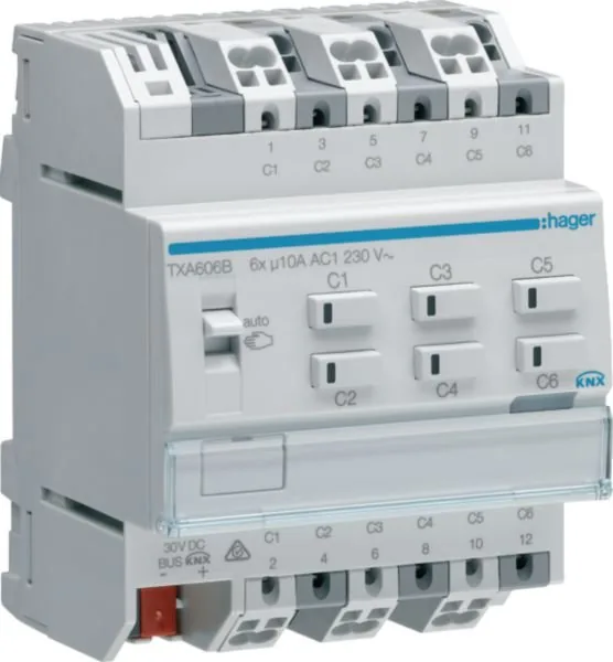
Fig. 1: example device variant 8/4gang
(1) Slide switch auto/
(2) KNX bus connection terminal
(3) Connections of loads
(4) Labelling field
(5) Illuminated programming button
(6) Operation button for manual operation per
output with status LED
(7) Connections for switching voltage
(8) Mains power supply connections (only 8gang)
With variants 4/2gang, 6/3gang and
10/5gang the basic design corresponds to the
8/4gang device variant.
Function
System information
This device is a product of KNX system and corre-
sponds to the KNX guidelines. Detailed special-
ised knowledge obtained from KNX training cours-
es is required for comprehension. The planning,
installation and commissioning of the device is
carried out with the help of KNX-certified software.
Systemlink commissioning
The function of the device is software-depend-
ent. The software is to be taken from the product
database. You can find the latest version of the
product database, technical descriptions as well
as conversion and additional support programmes
on our website.
Easylink commissioning
The function of the device is configuration-de-
pendent. The configuration can also be done using
devices developed specially for simple setting and
start-up.
This type of configuration is only possible with
devices of the easylink system. Easylink stands for
easy, visually supported start-up. Preconfigured
standard functions are assigned to the in/outputs
by means of a service module.
Functional description
The device receives telegrams from sensors or
other controllers via the KNX installation bus and
switches electrical loads with its independent relay
contacts.
Correct use
-Switch electrical loads of 230 V AC with poten-
tial-free contacts.
-Switching electrically operated motors of 230 V
AC for blinds, shutters, awnings and similar
hangings.
-Mounting on DIN rail according to DIN EN
60715 in the distribution box.
Product characteristics
-Manual activation of the outputs on the device
possible, building site operation.
-Status display of the outputs on the device.
-Scene functio.n
-Forced position by higher-level controller.
-Connection of various external conductors
possible.
Functions in switch operation
-Time switching functions.
Functions in roller shutter/blind operation
-Position can be started directly.
-Slat position directly controllable.
-Feedback of operating state, shutter position
and slat adjustment.
-3 Alarms.
Operation
Manual operation switch on/o
With the 8/4gang variants, control of the out-
puts is possible even without bus voltage when
mains voltage is connected e.g. for operation at
building sites.
Bus or mains power supply is present.
zPush switch (1) to position
.
Manual operation is switched on, the outputs
can be controlled using the operation buttons
(6) independently of each other.
During manual operation, the controller is deac-
tivated via the KNX bus.
Systemlink commissioning:
depending on the programming, the manual
operation is activated permanently or for a time
period configured via the application software.
If the manual operation is blocked via the appli-
cation software, no activation takes place.
Or
zMove switch (1) to position auto.
The manual operation is switched o. Oper-
ation takes place solely via the KNX bus. The
output adopts the position predefined by the
bus controller.
Operating outputs in manual operation
Operation takes place per output by briefly press-
ing the operation button repeatedly (Table 1).
CAUTION!
Risk of destruction due to simultane-
ous pressing of the buttons for UP and
DOWN if a motor is connected when
the motor is in unprogrammed state!
Motors, hangings and the device may
be destroyed!
Always only press one button in man-
ual operation for unprogrammed
devices.
ç
Status Behaviour when
button pressed briefly
Switching operation
Load is switched
o, status LED
of the button (6)
is o.
Switch ON the connected
load. Status LED of button
(6) lights up.
Load is switched
on, status LED
of the button (6)
lights up.
Switch OFF the connected
load. LED goes out.
Roller shutter/blind operation
Output is in stand-
by, status LED
of the button (6)
is o.
Movement operation starts.
Status LED of button (6)
lights up
1)
.
When the roller shutter/
blind is in final position,
the button opposite must
be pressed to move the
shutter/blind.
Output active,
status LED of the
button (6) lights
up
1)
.
Movement operation stops,
LED goes out.
1)
LED lights up red with TYA6.. devices. LED lights up
red while moving up and green while moving down
with TXA6.. devices.
Table 1: manual operation
Information for electricians
Installation and electrical connection
DANGER!
Touching live parts can result in an
electric shock!
An electric shock can be lethal!
Disconnect the connecting cables
before working on the device and
cover all live parts in the area!
ç
CAUTION!
Impermissible heating if the load of
the device is too high!
The device and the connected cables
may get damaged in the connection
area!
Do not exceed the maximum current
carrying capacity!
ç
CAUTION!
Risk of destruction if parallel connec-
tion of several motors on one output!
Final position switches could fuse
together. Motors, hangings and the
device may be destroyed!
Only connect one motor per
output!
ç
Installing the appliance
Observe temperature range. Provide sucient
cooling.
zMount device onto DIN rail in accordance with
DIN EN 60715.
Connect device
30V DC
-
+
auto
C6
C5
C8C8
C7C7
9
11
C5C6
13
C7
15
C8
10
12
1416
C5C6C7C8
3
5
C2C3
7
C4
4
6
8
C2C3C4
C2C2
C1C1
C4C4
C3C3
1
N
L
C1
2
C1
L3
L2
L1
N
Fig 2: Device connection
Fig 3: installation/deinstallation with plug-in termi-
nals
zConnect bus cable via connecting terminal (2).
Mains voltage can be connected optionally for
device variants 8/4gang (8). Reduction of the
power supply load is possible (see Technical
data).
Connecting loads to be switched
The output is configured as switching output.
zConnect switching voltage on the upper termi-
nal strip (7) of the device.
zConnect load on the lower terminal strip (3) of
the device.
Connecting blind drives
The two adjacent relay outputs C1/C2, C3/C4, C5/
C6, C7/C8 each form one blind output for blind
operations. Each left relay output C1, C3, C5, C7
is intended for the direction UP, each right relay
output C2, C4, C6, C8 is intended for the direction
DOWN. In manual operation, the blind is moved
UP and DOWN using the corresponding operation
buttons.
Two outputs are configured as blind output.
zConnect supply voltage of the drives on the
upper terminal strip (7). While doing so, use the
same phase (external conductors).
zConnect drives on the lower terminal strip (3).
Start-up
Systemlink: loading physical address and
application software
The switch (1) is in position auto.
zSwitch on bus voltage.
zPress programming button (5).
The button lights up.
If the button does not light up, no bus voltage
is present.
zLoad the physical address into the device.
Status LED of the button goes out.
zLoad application software.
zNote down the physical address on the label-
ling field (4).
Easylink:
Information on the system configuration can be
taken from the extensive description of the service
module easylink.
Start up the device
zSwitch on mains voltage on the outputs.
zSwitch on main power supply (8gang variant).
Determine operation time and slat adjusting
time
In blind/roller shutter operation, the operation time
for positioning the sunshade is important. The
position is calculated based on the operation time.
The slat adjusting time for slat blinds, determined
by the design, is part of the total operation time.
The opening angle of the slats is therefore set
as operation time between opened and closed
position.
The operation time for UP is normally longer
than the operation time for DOWN and must be
measured separately if necessary.
zMeasure UP and DOWN operation time of the
hanging.
zMeasure slat adjusting time between OPEN
and CLOSED.
zEnter measured values into the parameter set-
ting – running time... or slat step time.
Functional test
The functionality of the outputs is displayed via the
status LED of the operation button (6).
Appendix
Technical data
Supply voltage KNX 21-32VsSELV
Breaking capacity µ 10A AC1 230V~
Incandescent lamps 1200 W
HV halogen lamps 1200 W
Conventional transformers 1200 W electronic
transformers 1000 W
Fluorescent lamps:
-without ballast 1000 W
-with electronic ballast (mono/duo) 15 x 36 W
Energy-saving/LED lamps 12 x 23 W
Switching current at cos Φ = 0.6 max. 6 A
Upstream protection: circuit breaker 10 A
Minimum switching current 100 mA
Interlock time for
changing direction of travel software-dependent
Operating altitude max. 2000 m
Degree of contamination 2
Surge voltage 4 kV
Degree of protection of housing IP20
Degree of protection of housing under front panel
IP30
Impact protection IK 04
Overvoltage class III
Operating temperature -5° ... +45°C
Storage/transport temperature -20 … +70°C
Maximum switching cycle rate
at full load 6 switching cycle/minute
Connection capacity 0.75 mm²…2.5 mm²
Communication media KNX TP 1
Configuration mode S-Mode, Easy link
controller (TXA... only)
Variants 4/2gang
Energy dissipation 3 W
Permissible highest current strength per device
max. 30 A
Own consumption on the KNX bus:
-typical 4 mA (TYA..)
5 mA (TXA..)
-in standby 3,3 mA (TYA..)
3 mA (TXA..)
Dimension 4 TE, 4 x 17.5 mm
Variants 6/3gang
Energy dissipation 5 W
Permissible highest current strength per device
max. 45 A
Own consumption on the KNX bus:
-typical 4,3 mA (TYA..)
5 mA (TXA..)
-in standby 3,3 mA (TYA..)
3 mA (TXA..)
Dimension 4 TE, 4 x 17.5 mm
Variants 8/4gang
Auxiliary voltage 230V~ +10/-15%
240V~ +/-6%
Energy dissipation 6 W
Permissible highest current strength per device
max. 60 A
Own consumption on the KNX bus:
-typical 15,2 (TYA..)
6 mA (TXA..)
-in standby 8,6 mA (TYA..)
4 mA (TXA..)
Own consumption on the KNX bus with mains
connection:
-typical 2 mA (TXA.., TYA..)
-in standby 2 mA (TXA.., TYA..)
Dimension 6 TE, 6 x 17.5 mm
Variants 10/5gang
Energy dissipation 7 W
Permissible highest current strength per device
max. 75 A
Own consumption on the KNX bus:
-typical 15,9 mA (TYA..)
6 mA (TXA..)
-in standby 7,5 mA (TYA..)
4 mA (TXA..)
Dimension 6 TE, 6 x 17.5 mm
Troubleshooting
Manual operation not possible
Cause 1: switch (1) not moved to
.
Move switch to
.
Cause 2: manual operation has not been enabled
(Systemlink).
Enable manual operation via application soft-
ware.
Bus operation is not possible
Cause 1: bus voltage is not present.
Check bus connection terminals for correct
polarity.
Check bus voltage by briefly pressing the pro-
gramming button (5), red LED lights up if bus
voltage is present.
8gang: If mains voltage without bus voltage is
present - red LED of programming button (5)
flashes.
Cause 2: manual operation is active. Switch (1) is
in position
.
Move switch (1) to position auto.
Shutters/blinds do not move to the final
position
Cause: operation time for the shutters/blinds set
incorrectly.
Check operation times. Measure again and
reprogram if necessary.
WARNING!
The supply voltages of the electric
circuits connected to the product
must always all fall within the same
voltage range (LV (low voltage), VLV
(very-low voltage) or SELV (safety
extra-low voltage)).
Connecting voltages of dierent
ranges is strictly prohibited.
ç
Correct Disposal of This product
(Waste Electrical & Electronic
Equipment).
(Applicable in the European Union and other European
countries with separate collection systems).
This marking shown on the product or its literature
indicates that it hould not be disposed with other
household wasted at the end of its working life. To prevent
possible harm to the environment or human health from
uncontrolled waste disposal, please separate this from
other types of wastes and recycle it responsibly to
promote the sustainable reuse of material resources.
Household users should contact either the retailer where
they purchased this product, or their local government
oce, for details of where and how they can take this item
for environmentally safe recycling.
Business users should contact their supplier and check
the terms and conditions of the purchase contract. This
product should not be mixed with other commercial
wastes of disposal.
Usable in all Europe
å
and in Switzerland
z
/1
%
Quick check
I'm not a robot
Incorrect answer, please try again.
Chat with your Hager KNX Switching/Roller Shutter Actuator 6/3-way 10A manual using AI
Get instant AI answers from your Hager KNX Switching/Roller Shutter Actuator 6/3-way 10A manual
Ask anything about the Hager KNX Switching/Roller Shutter Actuator 6/3-way 10A. Answers come from this manual, with the pages they are based on.
Ask a Question
0/1000
Do you recommend KNX Switching/Roller Shutter Actuator 6/3-way 10A?
YesNo
Frequently Asked
Questions
A
The device requires a supply voltage on the KNX bus within the range of 21 to 32 volts direct current for proper operation.
Is this answer helpful?
A
Strictly one motor must be connected per output to avoid destruction of the device or the motor itself due to overload.
Is this answer helpful?
A
Yes, with mains voltage present, the manual operation switch allows control of outputs independently of the KNX bus network state.
Is this answer helpful?
A
The maximum permissible current strength is rated at 10 amperes alternating current for resistive loads under standard conditions.
Is this answer helpful?
A
Yes, the device supports rolling shutter and blind operations including slat position adjustment and position feedback capabilities.
Is this answer helpful?
A
The unit operates safely between negative five degrees Celsius and positive forty-five degrees Celsius ambient temperature.
Is this answer helpful?
A
Yes, the device is designed to mount on a standard DIN rail in accordance with DIN EN 60715 specifications.
Is this answer helpful?
M: QW-35-FL
Advantagesand
Disadvantages
Advantages
Supports KNX system standardization for unified automation control
Includes manual operation override for maintenance situations
Compact 4TE design saves space in distribution cabinets
Status LEDs provide immediate feedback on output states
Capable of handling both switching and blind drive loads
VS
Disadvantages
Requires qualified electrician for safe installation and wiring
Only allows one motor per output channel restriction
Cannot connect three phase motors directly to outputs
Needs KNX certified software for full configuration access
Bus voltage required for normal operation modes
M: QW-35-FL
Product
Specification
Type
Actuator
Standard
KNX
Function
Switching actuator (on/off), blind control
Topology
Bus
Special Features
IP20, IP30, IK04
M: QW-35-FL
Product
Description
Introduction To Smart Switching
Welcome to modern building technology utilizing the Hager KNX Switching/Roller Shutter Actuator 6/3-way, 10A, 4TE REG Switching Actuator Manual specifications. This device transforms standard electrical infrastructure into intelligent control centers. Homeowners gain access to automated lighting and shading management without complex wiring changes. The compact form factor fits neatly into existing distribution boards efficiently. Professional installers recognize the high quality components used in production runs. Reliability remains the primary focus of engineering teams developing these modules. Safety features protect against electrical shocks during routine maintenance activities.
Operational Flexibility Explained
Functionality extends beyond basic power interruption capabilities significantly. Roller shutter drives receive precise commands to adjust fabric heights automatically. Slat adjustment timing allows users to optimize natural light penetration indoors. Scene functions enable rapid mode changes across multiple rooms simultaneously. Forced position controls ensure consistency when overridden by central servers. Status LEDs illuminate rapidly to signal current output conditions instantly. Manual buttons operate locally even if the bus network disconnects temporarily. This redundancy enhances user confidence during unexpected outage scenarios.
Technical Precision and Safety
Electricians must verify voltage ranges before connecting live supplies securely. One motor per output restriction prevents overheating and mechanical failure issues. Three phase connections remain prohibited due to incompatible internal circuitry designs. Minimum switching currents dictate compatibility with specific electronic transformer loads. Surge protection classes define resilience against lightning strikes and grid fluctuations. Environmental ratings specify safe storage and transport temperature boundaries clearly. Wiring capacity accepts standard cable sizes ranging from half to two point five square millimeters. Secure locking mechanisms hold terminals firmly during vibration events.
Commissioning Procedures Overview
Software configuration steps require KNX certified tools for correct parameter loading. Physical address assignment establishes unique identity on the shared communication line. Bus voltage presence confirms proper network continuity before starting operations. Application logic determines if outputs behave as simple switches or blind drives. Troubleshooting flows guide technicians through common error states quickly. Recalibration ensures movement stops match physical stoppers on window frames. Regular firmware updates maintain compatibility with evolving sensor inputs. Proper disposal follows environmental laws regarding electronic waste recycling globally.
Summary Of Benefits
Selecting this product secures a foundation for scalable automation growth. Performance metrics meet rigorous international testing benchmarks consistently. Compact dimensions save expensive space inside crowded meter cabinets effectively. Energy usage stays low reducing monthly electricity bills noticeably. Customer support teams provide documentation for every installed batch reliably. Long term investment value exceeds initial purchase price considerations. Trustworthy brands deliver peace of mind through extended warranty periods. Continuous innovation ensures legacy compatibility with next generation smart homes. Installation processes are straightforward for experienced personnel.