
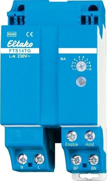
Eltako FTS14TG Manual
PDF manual · 2 Pages
English



Quick check
Incorrect answer, please try again.
Chat with your Eltako FTS14TG manual using AI
Get instant AI answers from your Eltako FTS14TG manual
Ask anything about the Eltako FTS14TG. Answers come from this manual, with the pages they are based on.
Ask a Question
Do you recommend FTS14TG?
Yes NoFrequently Asked Questions
The device features an exceptionally low standby loss of only 1.3 watts which contributes to energy efficiency during periods when the system is idle but powered on.
Is this answer helpful?
A single pushbutton gateway can support up to thirty bus switches or pushbutton bus couplers connected over the two-wire bus link for integrated control.
Is this answer helpful?
Yes, operation works in conjunction with FAM14 or FTS14KS devices allowing telegrams to be transmitted over the building wireless system alongside wired connections.
Is this answer helpful?
LED displays show operational status including actuator confirmations on the red light and button presses on the green light to help identify system state quickly.
Is this answer helpful?
Only skilled electricians may install this electrical equipment otherwise there is a risk of fire or electric shock requiring strict adherence to safety guidelines.
Is this answer helpful?
The permitted maximum line length is 200 meters ensuring sufficient reach for most building layouts while maintaining reliable data transfer integrity.
Is this answer helpful?
Advantages and Disadvantages
Advantages

- Extremely low standby power consumption of only 1.3 watts ensures significant long-term energy savings.
- Modular design fits standard DIN-EN rails occupying just 2.5 modules of space for compact installation.
- Combines data transfer and power supply over a single two-wire link reducing cable clutter.
- Connects up to thirty compatible bus switches or couplers to a single gateway unit efficiently.
- Compatible with wireless systems like FAM14 allowing flexible command transmission strategies.
Disadvantages

- Requires skilled electricians to install due to risks of fire or electric shock from wiring.
- Maximum permitted line length is limited to 200 meters for optimal signal stability.
- Needs specific ventilation gaps on the left-hand side to prevent overheating during operation.
- Must match specific device families such as FTS61BTK or B4T65 for full functionality.
- Clearing ID addresses involves specific multi-step rotary switch procedures that take time.
Product Specification
Type
Hardware Control Unit
Standard
EnOcean, RS485
Function
Gateway
Topology
Bus
Features
IP20
Product Description
Introduction to the Eltako FTS14TG Gateway
The Eltako FTS14TG RS485-Bus Pushbutton-Gateway revolutionizes how modern facilities handle automated control tasks through its highly efficient design. This modular unit fits onto standard DIN-EN rails and requires only 2.5 modules of physical space on your rack. One of its strongest advantages is the remarkably low standby power loss which consumes merely 1.3 watts even during idle periods ensuring significant energy savings over time. The device effectively bridges the gap between traditional pushbutton panels and sophisticated automation networks used today. By supporting connections to up to thirty compatible bus switches or couplers simultaneously it drastically reduces cabling complexity and installation labor. Data signals combined with necessary electrical power travel together over a straightforward two-wire link that minimizes overall material costs for contractors.
Integration and Flexibility
Seamless integration into existing Eltako structures is possible because the gateway communicates directly with the RS485 bus infrastructure reliably. This setup allows for centralized management alongside decentralized switching logic required for complex building projects. Users can operate the system alongside FAM14 or FTS14KS units to enable wireless commands without sacrificing wired reliability for critical applications. Proper heat dissipation requires careful planning with a ventilation gap specified during mounting to maintain optimal performance across all operational temperature ranges. The unit supports multiple operating modes allowing different addressing schemes depending on specific application needs found in varying environments. Whether implementing direction-based controls or separate identity assignments this hardware adapts easily to unique project requirements without extensive reconfiguration efforts later on.
Safety and Configuration
Installation must strictly follow industry regulations and performed by qualified professionals due to voltage risks involved with electrical work. Internal LEDs provide essential visual feedback regarding data packets and confirmation signals making initial troubleshooting straightforward for maintenance technicians. Clearing IDs and assigning addresses follows a precise manual procedure using rotary switches located conveniently on the front panel for accessibility. Connectivity lengths can extend up to two hundred meters theoretically though line quality determines actual stability thresholds accurately. The termination resistor must be placed correctly to ensure signal integrity along the entire network chain connecting all devices together effectively. With support for various switch types like B4T65 models engineers gain maximum flexibility in interface selection matching specific customer demands. This solution eliminates the need for additional gateways when scaling up small residential setups while remaining robust enough for larger commercial environments requiring high availability standards throughout daily operations. Configuration is simplified further when utilizing the dedicated PC tool software which assists in creating device lists and managing actuator identities efficiently. Operators can modify addresses and verify connections remotely before final deployment occurs onsite avoiding costly errors.
Search for 67,706 Manuals online


Type-in Brand or Model