Manual.ly Logo

Eltako FTS14EM Manual

0.0 · 0 Ratings

PDF manual · 2 Pages

English

M: QW-35-FL
page

/ 2

Loading...
3775e5a84cb84fc27d2dc8acf281a2186bf8 page 1
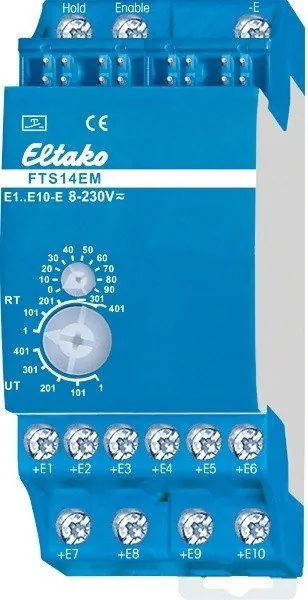
Input module
FTS14EM
Input module for the Eltako RS485 bus,
10 control inputs for universal control
voltage. Only 0.1 watt standby loss.
Modular device for DIN-EN 60715 TH35
railmounting. 2 modules = 36 mm wide,
58 mm deep.
Connection to the Eltako-RS485 bus. Bus
cross wiring and power supply with jumper.
Operation in conjunction with FTS14KS or
FAM14.
A 12 V DC voltage is supplied from a switching
power supply unit FSNT14-12V/12W which
has a width of only 1 module.
10 control inputs +E1 to +E10/-E electrically
isolated from the supply voltage. Control
voltage: 8..230 V UC.
The control inputs can be either activated
for pushbuttons (delivery state), window-
door contacts or motion detectors.
From the production week 21/19 the signals
of the control inputs can be inverted.
Control inputs for pushbuttons:
telegrams of pushbuttons will be generated
(e.g. 0x70). Each FTS14EM can be set to UT
(= universal pushbutton) or RT (= direction
pushbutton) on the lower rotary switch.
Control inputs for window-door contacts:
telegrams of the window-door contact FTK
are generated (EEP D5-00-01). If the input is
driven by the contact with the control voltage
GB
Temperature at mounting location:
-20°C up to +50°C.
Storage temperature: -25°C up to +70°C.
Relative humidity:
annual average value <75%.
30 014 060 - 3
Only skilled electricians may install this
electrical equipment otherwise there is
the risk of  re or electric shock!
valid for devices from production week
11/21 (see bottom side of housing)
to be applied externally, the telegram 'window
open' is generated. If the windows-door
contact is opened, the telegram 'window
open' is generated. As with the wireless
sensor FTK, the status telegram is repeated
every 15 minutes.
Control inputs for motion detectors:
telegrams of the wireless motion/brightness
sensor FBH are generated (EEP A5-08-01),
wherein the brightness value is always 0. If
the input is driven by the motion-detectors-
contact with the control voltage to be
applied externally, the telegram 'motion' is
generated. If the contact is opened, the
telegra 'no motion' will be generated. As
with the wireless sensors FBH, the status
telegram is repeated every 15 minutes.
Each telegram of a contact input has to be
taught-in with an identi cation number (ID)
into one or more actuators according to the
operating instructions.
Function rotary switches
The lower rotary switch de nes the group
to which an FTS14EM belongs. A total of 5
groups are available (1, 101, 201, 301 and 401)
each with 100 IDs. The upper rotary switch
(0 to 90) sets the ID within a group. The ID
range within a group results from the com-
bination of upper and lower rotary switches
and must be set differently on each FTS14EM.
Maximum ten FTS14EMs form a group. There-
fore, a total of 50 FTS14EMs comprising 500
pushbuttons or contacts are possible in one
RS485 bus.
To generate the necessary teach-in telegrams
for teaching-in into the actuators, the re-
quested group has to be selected on the
upper and lower rotary switch. For push-
buttons in the range UT or RT or for window-
door contacts and motion sensors in the
range RT. Then con rm the required control
input.
In operation, the same group must be selected
in the range UT or RT for push buttons or UT
for window/door contacts and motion sensors.
The LED below the upper rotary switch  ashes
brie y, when a connected contact is closed.
Optional: An FAM14 wireless antenna module
(from Wireless Building System) which is only
two modules wide can also be installed.
Actuators can then be activated via the
FTS14EM by wireless pushbuttons and
contacts, hand-held transmitters and wireless
sensors in addition to conventional buttons.
As the FAM14 has an integrated switch mode
power supply unit, the FTS14KS is no longer
required for power supply in this con guration.
The bidirectional FAM14 also permits a
Smart Home central unit SafeIV to evaluate
feedback messages from the actuators
transferred by wireless. Each actuator status
is then displayed and can also be changed.
Connecting the HOLD terminals of all devices
regulates bus access and prevents collisions.
The telegrams of the FTS14EM and FTS14KEM
can also be sent to the Eltako Wireless Building
with the optional wireless output module
FTS14FA.
All hold terminals of the FTS14EM must be
connected to the hold terminal of the
FTS14KS or FAM14.
When 1 to 10 FTS14EMs are used, the HOLD
terminal on one FTS14EM must be connected
to the Enable terminal.
When 11 to 20 FTS14EMs are used, the
HOLD terminal on two FTS14EMs must be
connected to the Enable terminal.
When 21 to 30 FTS14EMs are used, the
HOLD terminal on three FTS14EMs must be
connected to the Enable terminal.
When 31 to 40 FTS14EMs are used, the
HOLD terminal on four FTS14EMs must be
connected to the Enable terminal.
When 41 to 50 FTS14EMs are used, the
HOLD terminal on  ve FTS14EMs must be
connected to the Enable terminal.
Activate the inputs for pushbuttons (factory
setting):
turn the lower rotary switch within 3 seconds
5 times to the left stop, the LED goes on during
2 seconds.
Activate the inputs for window/door con-
tacts: turn the upper rotary switch within
3 seconds 5 times to the left stop, the LED
goes on during 4 seconds.
Activate the inputs for motion sensors:
turn the upper rotary switch within 3 seconds
5 times to the right stop, the LED goes on
during 6 seconds.
Invert the signals of the control inputs:
Turn the bottom rotary switch within 3 seconds
5 times to the right, the LED lights up for
2 seconds.
By activating the control inputs for buttons,
window-door contacts or motion detector
the inversion is cancelled.
10 control inputs = 10 universal push-
buttons UT:
E1 = 0x70 (FT4- top right)
E2 = 0x50 (FT4- bottom right)
E3 = 0x30 (FT4- top left)
E4 = 0x10 (FT4- bottom left)
E5 = 0x70
E6 = 0x50
E7 = 0x30
E8 = 0x10
E9 = 0x70
E10 = 0x50
If the control input E10 is controlled with a
switch, a wireless pushbutton telegram is
generated cyclically every 5 minutes.
10 control inputs = 5 direction push-
buttons RT:
E1/E2 send 70/50 (= pushbutton right side
top/bottom)
E3/E4 send 30/10 (= pushbutton left side
top/bottom)
E5/E6 send 70/50
E7/E8 send 30/10
E9/E10 send 70/50
IDs are generated in 'quasi-decimal' num-
bering in order to make it easier to convert
terminal numbering to the button IDs to be
entered in PCT14.
The ID numbers are therefore identical to
the input numbers. You only need to add
1000.
Lower rotary switch on UT:
Each input has a separate ID.
IDs of  rst group:
0x1001..0x1010 (pushbutton 1..10)
0x1011..0x1020
0x1021..0x1030
0x1031..0x1040

Chat with your Eltako FTS14EM manual using AI

Get instant AI answers from your Eltako FTS14EM manual

Ask anything about the Eltako FTS14EM. Answers come from this manual, with the pages they are based on.

Ask a Question

0/1000

Do you recommend FTS14EM?

Yes No

Frequently Asked Questions

A

The control voltage operates safely between eight and two hundred thirty volts AC or DC, ensuring compatibility with various sensor types and existing building infrastructure standards widely used today.

Is this answer helpful?

A

A total of ten FTS14EM modules can be grouped together allowing up to five hundred individual buttons or contacts per RS485 bus network segment with proper addressing.

Is this answer helpful?

A

Yes, optional integration with the FAM14 wireless antenna module permits activation via wireless pushbuttons and sensors without needing separate wired connections for every terminal.

Is this answer helpful?

A

No, signals can only be inverted for inputs driven by pushbuttons or window contacts if the device originates from production week twenty-one nineteen or later.

Is this answer helpful?

A

It connects to a switching power supply unit like FSNT14-12V providing necessary power while maintaining very low standby loss figures compared to competitors.

Is this answer helpful?

M: QW-35-FL

Advantages and Disadvantages

Advantages

  • Low standby power consumption of 0.1 Watts saves energy costs significantly over extended periods.
  • Modular DIN-EN rail mounting allows compact installation with easy expansion options readily available.
  • Versatile input support handles pushbuttons, windows, doors, and motion detectors with unified interface.
VS

Disadvantages

  • Requires skilled electricians for installation to prevent serious fire or electric shock risks.
  • Bus cross wiring and jumper configurations demand precise planning for complex network layouts.
  • Signal inversion feature is limited to devices produced from week twenty-one nineteen onwards.
M: QW-35-FL

Product Specification

Type

Sensor

Standard

EnOcean, RS485

Topology

Bus

Features

IP20

M: QW-35-FL

Product Description

Introduction to Smart Building Control

Modern building automation relies heavily on reliable input modules to connect physical controls with digital systems seamlessly. The Eltako FTS14EM Push Button Input Module, 10 Inputs, 2TE REG Manual specifications highlight its robust design specifically for RS485 bus integration within larger networks. This device serves as a cornerstone for creating responsive environments where user interaction drives complex system behaviors efficiently and safely.

Versatile Input Capabilities

The unit features ten universal control inputs capable of handling voltages ranging between eight volts and two hundred thirty volts AC or DC effectively. These inputs function flexibly for standard pushbuttons, window-door contacts, or motion detectors depending on the project needs. Engineers appreciate the electrical isolation of these inputs from the main supply voltage which enhances safety during routine maintenance and daily operation. Each input can be configured independently through software settings derived from the original documentation logic.

System Integration and Expansion

Connecting directly to the Eltako-RS485 bus allows seamless communication with remote actuators and intelligent central units easily. The hardware occupies minimal space, measuring just thirty-six millimeters wide across two TE modules on standard rails. Power consumption is incredibly low, with a standby loss of only one tenth watt reducing energy waste over time. Optional wireless capabilities are fully supported by adding the FAM14 antenna module locally. This addition enables remote activation via handheld transmitters and sensors without requiring additional heavy-duty cabling burdens throughout the building.

Installation and Configuration

Setup involves carefully configuring rotary switches to define groups and unique identification numbers within the network topology accurately. Ten devices can form a single logical group, supporting up to five hundred distinct inputs across the entire system hierarchy simultaneously. Technicians must strictly adhere to safety protocols at all times to ensure compliance with local electrical codes. Only qualified personnel should handle the live electrical connections to prevent potential fire hazards or electric shock risks during assembly. Proper wiring ensures stable telegram generation for all connected loads without interruption.

Operational Notes

Regular status updates occur automatically every fifteen minutes for contact inputs to maintain synchronization. Signal inversion is available for users starting from production week twenty-one nineteen onwards. Operators can select between universal pushbutton modes or directional modes depending on specific application requirements chosen initially. LED indicators provide immediate visual feedback when contacts close during functional testing phases. Adherence to manufacturer guidelines ensures maximum longevity and optimal performance in diverse temperature ranges from minus twenty degrees to plus fifty degrees Celsius during active usage cycles.

M: QW-35-FL

© Copyright 2026 Manual.ly