

Eltako FMZ14 Manual
PDF manual · 2 Pages
English



Quick check
Incorrect answer, please try again.
Chat with your Eltako FMZ14 manual using AI
Get instant AI answers from your Eltako FMZ14 manual
Ask anything about the Eltako FMZ14. Answers come from this manual, with the pages they are based on.
Ask a Question
Do you recommend FMZ14?
Yes NoFrequently Asked Questions
The device supports switching currents up to ten amperes at two hundred fifty volts AC. This capacity covers most standard residential and light commercial loads effectively. Ensure your wiring matches these limits.
Is this answer helpful?
It offers ten unique functions for precise timing control. These include delays, pulses, and toggles for various automation tasks.
Is this answer helpful?
Yes, it includes an RS485 bus connection. This allows communication within a larger control network for centralized management.
Is this answer helpful?
Both contacts default to an open position. This prevents unintended activation when power is restored to the system.
Is this answer helpful?
Yes, DX-Technology ensures switching at voltage zero-crossing. This reduces electrical stress and extends the lifespan of loads.
Is this answer helpful?
Specific dial combinations allow memory clearing. Follow the manufacturer guide for the exact sequence to restore settings.
Is this answer helpful?
Advantages and Disadvantages
Advantages

- Low standby power consumption of 0.4 watts saves energy effectively.
- DX-Technology reduces wear by switching at voltage zero crossings.
- Ten distinct functions allow flexible automation configurations easily.
- Integrated RS485 bus enables centralized network management.
Disadvantages

- Only qualified electricians should handle installation for safety reasons.
- Complex settings require careful configuration to function correctly.
- Power loss defaults contacts to open preventing auto-restart.
Product Specification
Type
Actuator
Standard
EnOcean, RS485
Function
Switching actuator (on/off)
Topology
Bus
Features
IP20
Product Description
Revolutionize Your Lighting and Automation with the Eltako FMZ14
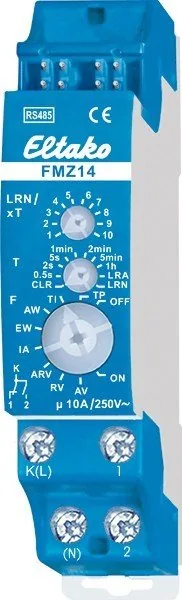
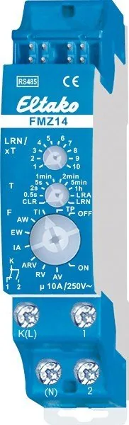
The Eltako FMZ14 Time Relay, 1TE REG, Switching Actuator Manual serves as the core reference for understanding this powerful device, though we focus on practical application here. This unit stands out in the market for its versatile design catering to modern smart building demands. It offers ten unique functions that allow for precise timing control in various electrical setups. Whether you need to manage lighting sequences or automate gate operations, this device provides the necessary logic.
Core Technology and Efficiency
Built with DX-Technology, the relay ensures contacts switch exactly at the voltage zero-crossing point. This innovation significantly extends the lifespan of connected loads by reducing electrical stress. The standby power consumption is remarkably low at 0.4 watts, making it energy efficient even when idle. The device accepts a wide range of input voltages and supports switching currents up to ten amperes at two hundred fifty volts AC. These ratings ensure compatibility with most standard household and office appliances without requiring external converters.
Networking and Sensor Integration
Installation is streamlined through direct mounting onto standard DIN rails measuring thirty-five millimeters. Connectivity is enhanced via an integrated RS485 bus connection that facilitates communication within a broader control network. You can link radio window and door contacts directly to the actuator for advanced security features. The system learns opener and closer commands from external sensors automatically. Additionally, direction buttons can be assigned specific start and stop commands for complex motorized tasks.
User Configuration and Maintenance
Configuration is handled intuitively using three rotary switches located on the front face. The upper switch manages the base time, while the middle dial sets the multiplier. Selection of the operating mode occurs via the bottom switch, offering options like pulse timers, delay on, or delay off. An LED indicator provides visual feedback during setup and operation. Advanced users may utilize PC tools for further customization of parameters. Resetting the device memory is also straightforward through specific dial combinations.
Safety Standards and Operation
Safety guidelines dictate that only qualified professionals should perform the physical installation to avoid fire or shock hazards. Operating temperatures range from negative twenty to positive fifty degrees Celsius under normal conditions. The unit defaults to an open state during power failures to ensure safe deactivation. Regular maintenance checks help maintain optimal performance over time. Adhering to these specifications guarantees reliable operation within your automated environment. Trust the Eltako engineering for robust industrial grade components in consumer spaces.
Note: Ensure all electrical connections comply with local regulations before energizing the system. Keep spare units accessible for quick replacement in critical infrastructure. Verify warranty terms prior to final deployment. This approach minimizes downtime.
Search for 67,706 Manuals online


Type-in Brand or Model