
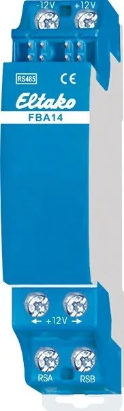


Eltako FBA14 Manual
PDF manual · 1 Pages
English


Quick check
Incorrect answer, please try again.
Chat with your Eltako FBA14 manual using AI
Get instant AI answers from your Eltako FBA14 manual
Ask anything about the Eltako FBA14. Answers come from this manual, with the pages they are based on.
Ask a Question
Do you recommend FBA14?
Yes NoFrequently Asked Questions
It acts as a bus coupler for wire connections of bus and power supply jumpers in Series 14 devices.
Is this answer helpful?
Each module is 18mm wide and 58mm deep for compact mounting.
Is this answer helpful?
The total length of all connecting lines should not exceed 100m.
Is this answer helpful?
Yes, a switch mode power supply unit FSNT12-12V/12W can be connected for redundancy.
Is this answer helpful?
Only skilled electricians may install this equipment to prevent shock or fire risk.
Is this answer helpful?
A 9mm wide resistor must be plugged into the last actuator in the chain.
Is this answer helpful?
Storage temperature ranges from minus twenty-five to positive seventy degrees Celsius.
Is this answer helpful?
Advantages and Disadvantages
Advantages

- Modular DIN rail design fits 18mm spacing standard
- Supports power supply redundancy for high availability
- Enables long distance connections up to 100 meters
- Compatible with screened bus lines for noise reduction
Disadvantages

- Requires installation by skilled electricians only
- Strict temperature limits affect outdoor mounting
- Jumper settings must be precise for redundancy
- Specific terminating resistor required at last actuator
Product Specification
Type
Control Unit Hardware
Standard
EnOcean, RS485
Function
Gateway
Topology
Bus
Product Description
Comprehensive Guide to Building Automation Components
Modern building automation relies heavily on stable communication protocols between modular devices to ensure optimal performance. The Eltako FBA14 RS485 bus coupler Manual offers detailed insights into how this unit facilitates robust connectivity within industrial environments. It functions as a bridge allowing wire connections for both bus signals and power supply jumpers seamlessly. This modular device is designed specifically for DIN-EN 60715 TH35 rail mounting within standard electrical panels. With a compact footprint of one module equaling 18mm wide and 58mm deep, it saves significant space in crowded electrical cabinets.
Technical Installation Requirements and Dimensions
Users can connect various bus parts easily using this coupler to manage complex circuits. Parts located on different DIN rails or in separate distributors get linked via an FBA14 unit effectively. Connection utilizes a four-wire screened bus line, often resembling standard telephone wiring infrastructure for simplicity. Total lengths of all connecting lines should strictly not exceed 100m to preserve signal quality over distance. A specific 9mm wide second terminating resistor must be plugged into the last actuator position for stability. These resistors usually come supplied with related FAM14 or FTS14KS models for completeness. Positioning flexibility allows placement anywhere within the Series 14 device row sequence without issues.
Power Management and Terminal Connections Explained
Wiring involves the four main bus line wires attached to -12V, +12V, RSA, and RSB terminals correctly. Two FBA14s link together via these specific connections to synchronize operations. The factory jumper plugged into the lower terminal block connects to +12V and must remain fitted initially. This jumper stays fitted even when a switch mode power supply unit FSNT12-12V/12W creates redundancy power connections reliably. If the existing switch mode supply proves insufficient for the whole RS485 bus, additional capacity becomes necessary for survival. Removing the jumper allows a dedicated supply unit to increase total power capacity directly for heavy loads.
Safety Guidelines and Operational Specifications
Actuators positioned left of the bus coupler receive power from FAM14 or FTS14KS sources primarily. Units to the right pull power from the dedicated switch mode supply unit independently. Safety remains paramount during any setup phase to protect personnel. Only skilled electricians may install this electrical equipment safely to avoid hazards. Failure to comply risks fire or electric shock incidents significantly within facilities. Temperature limits apply strictly at the mounting location ranging from minus twenty degrees to plus fifty degrees Celsius. Storage temperature tolerances span between negative twenty-five and positive seventy degrees Celsius annually. Relative humidity must stay below an average value of seventy-five percent. Always consult official resources like the Eltako FBA14 RS485 bus coupler Manual for complete compliance.
Notes on Maintenance and Longevity
Integration stability defines successful automation projects for years. Using this coupling method simplifies troubleshooting across complex layouts significantly. The split power supply configuration helps prevent single points of failure within the network topology entirely. By separating actuator power zones, technicians isolate faults more rapidly during maintenance cycles effectively. Reliability scores improve when adhering to the specified wiring diagrams found in technical literature consistently.
Search for 67,706 Manuals online


Type-in Brand or Model