
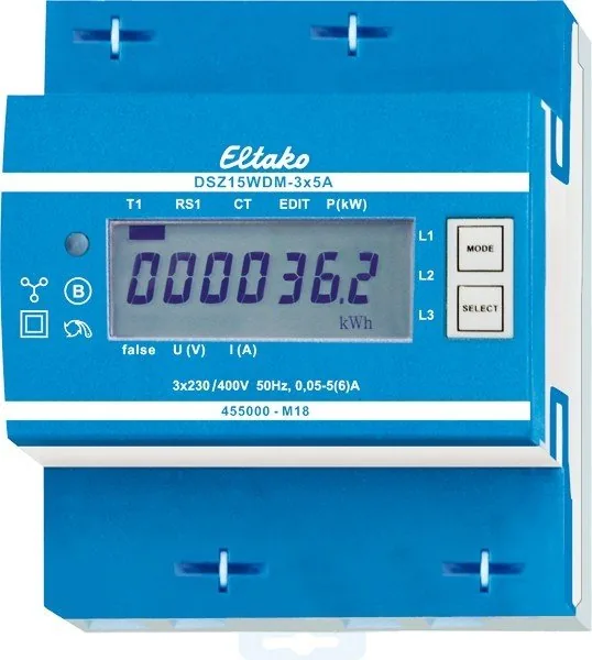
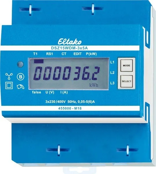
Eltako DSZ15WDM-3x5A Manual
PDF manual · 2 Pages
English



Quick check
Incorrect answer, please try again.
Chat with your Eltako DSZ15WDM-3x5A manual using AI
Get instant AI answers from your Eltako DSZ15WDM-3x5A manual
Ask anything about the Eltako DSZ15WDM-3x5A. Answers come from this manual, with the pages they are based on.
Ask a Question
Do you recommend DSZ15WDM-3x5A?
Yes NoFrequently Asked Questions
Hold the Select button for three seconds to enter the menu. Press Mode to increment by ten and Select to increment by one. Wait for the main menu to return after setting your desired value.
Is this answer helpful?
It operates with accuracy class B which allows a variance of plus or minus one percent from true values under specified conditions.
Is this answer helpful?
Yes, the seven segment LC display remains readable for two weeks without power supply due to non volatile memory storage.
Is this answer helpful?
No, the energy meter is designed for indoor use exclusively within specified environmental classes M1 and E2 for optimal safety.
Is this answer helpful?
You can connect one, two, or three converters with secondary currents up to five Amperes depending on your installation needs.
Is this answer helpful?
Consumption values are saved in EEPROM memory which prevents data loss during power interruptions and ensures immediate recovery.
Is this answer helpful?
If conductor direction is wrong the screen shows false text along with the specific outer conductor identified for correction.
Is this answer helpful?
Advantages and Disadvantages
Advantages

- Class B accuracy ensures measurements stay within plus minus one percent tolerance reliably.
- Low standby loss of half watt per path conserves power without impacting readings.
- Non volatile memory retains data immediately after power fails completely.
- Adjustable CT ratios scale from five to fifteen hundred to fit various transformers.
- M Bus interface supports automated data transfer and remote address updates.
Disadvantages

- Installation requires skilled electricians to avoid fire risk or electric shock.
- Rated for indoor use only limiting deployment in harsh weather conditions.
- IP50 rating does not protect against water jets entering the device.
- Fixed DIN rail footprint may not suit compact panel designs easily.
- Error detection displays text warnings instead of color coded indicators.
Product Specification
Type
Sensor
Function
Current measurement
Topology
Bus
Features
IP20, Display
Product Description
Advanced Energy Monitoring Systems
Effective management requires precision instruments. The Eltako DSZ15WDM-3x5A M-Bus Converter Meter 3-Phase 4TE REG Current/Energy Meter Manual guides users through configuring advanced metering devices. This three-phase unit measures active energy efficiently using integrated current sensors. Standby consumption stays minimal at 0.5 watt per path ensuring efficiency is maintained throughout operation cycles without significant drain on grid resources. Rated for 3x5 A maximum current makes it ideal for commercial loads needing detailed breakdowns.
Measurement Capabilities
Accuracy class B provides reliable data within one percent variance limits for regulatory compliance purposes. Device internal power consumption remains unmeasured to preserve user billing integrity fully. Stored consumption values persist in nonvolatile memory even after unexpected electricity cuts occur. Display recovers instantly upon restoration thanks to built-in flash storage mechanisms handling log history effectively. Seven segment LC readouts offer legibility for up to two weeks without external power supply present.
Configuration Settings
Users can modify CT ratios using jumper bridges located near marked terminals on the casing exterior. Default factory setting locks at five to five ratios until removal allows custom adjustments matching installed equipment specifications. Supported ratios extend far beyond standard values going up to fifteen hundred divided five depending on transformer sizing requirements selected locally. Mbus interface transfers full register sets including voltage current and power factor information automatically every few minutes.
Operational Safety
Modular construction fits standard DINE 60715 TH35 rails occupying just four modules width wise measuring seventy mm total depth inside cabinet spaces. Connection involves four wires linking outer conductors to secondary side converter inputs securely protected by local regulation standards. Always connect N terminal first to guarantee correct phase sequencing during initial setup procedures completed by trained staff members only. Failure to observe polarity directions triggers false error states showing which conductor has reversed flow pattern detected visually.
Maintenance Requirements
Voltage monitoring saves all registers to EEPROM immediately when drops detected preventing data loss during transitions. Housing protects components maintaining IP50 rating suitable for indoor environments excluding wet zones. Temperature tolerance spans negative twentyfive to positive fiftyfive degrees Celsius safely operating outdoors if climate controlled internally. Relative humidity averages less than seventy five percent annually for long term reliability across years of continuous service daily. Keep documentation handy for reference during calibration events planned yearly intervals scheduled regularly by facility managers.
Notes: Disconnect voltage paths before touching current transformers to prevent shock risks entirely. Verify terminal torque settings match recommendations preventing loose connections causing overheating incidents over time. Consult technical support contacts if unusual error patterns emerge frequently affecting normal operations expected from units purchased recently. Manufacturer guarantees performance within stated environmental classes M1 and E2 covering basic interference immunity thresholds successfully met.
Search for 67,706 Manuals online


Type-in Brand or Model