
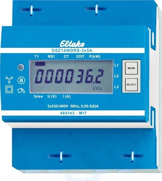
Eltako DSZ14WDRS-3x5A Manual
PDF manual · 2 Pages
English



Quick check
Incorrect answer, please try again.
Chat with your Eltako DSZ14WDRS-3x5A manual using AI
Get instant AI answers from your Eltako DSZ14WDRS-3x5A manual
Ask anything about the Eltako DSZ14WDRS-3x5A. Answers come from this manual, with the pages they are based on.
Ask a Question
Do you recommend DSZ14WDRS-3x5A?
Yes NoFrequently Asked Questions
It belongs to Accuracy class B which allows a deviation of plus or minus one percent. This ensures reliable billing and monitoring data for professional applications.
Is this answer helpful?
Yes, when connected to the FAM14 module, it transmits data to the wireless network. This allows remote access without direct cabling to the bus system.
Is this answer helpful?
Consumption values are stored in non-volatile memory. They are displayed again immediately after power returns without data loss.
Is this answer helpful?
The device functions safely between minus twenty-five degrees Celsius and plus fifty-five degrees Celsius. Storage limits extend to plus seventy degrees Celsius.
Is this answer helpful?
Only skilled electricians should install this equipment due to risks of shock or fire if mishandled. Voltage paths must be disconnected first.
Is this answer helpful?
It includes an RS485 interface for wired bus connections. The FAM14 adds wireless transmission capabilities for broader network integration.
Is this answer helpful?
Remove the bridge jumper marked JUMPER then reset the meter. Select the desired ratio like 500:5 then block the terminals again.
Is this answer helpful?
Advantages and Disadvantages
Advantages

- Low standby power consumption minimizes operational costs effectively.
- Non-volatile memory ensures data security during unexpected power outages.
- Wide adjustable CT ratios provide flexibility for various load profiles.
- Wireless data transmission capability via FAM14 module enables remote access.
- Secure DIN rail mounting design suits standard industrial cabinet layouts.
Disadvantages

- Requires skilled electrician for installation due to safety risks involved.
- Limited to five Ampere maximum current per phase without external transformers.
- Dependent on external converters for full wireless functionality implementation.
- Complex address assignment process may require specific tools initially.
- Fixed display brightness without user-adjustable setting options available.
Product Specification
Type
Sensor
Standard
RS485
Function
Current Measurement Function
Topology
Bus
Features
IP51, Display
Product Description
Comprehensive Power Measurement Technology
The Eltako DSZ14WDRS-3x5A RS485-Bus-Wireless-Converter serves as a cornerstone for efficient energy management in complex electrical environments. Designed specifically as a three-phase meter, it delivers accurate readings for both industrial and commercial sectors. Its ability to measure active energy by analyzing the current between input and output ensures high fidelity data collection. This reliability makes it suitable for facilities demanding strict compliance with energy standards.
Seamless Integration Capabilities
Connectivity remains a primary strength with the built-in RS485 interface supporting various bus protocols. You can utilize the FBA14 component to link the device directly to the Eltako RS485 bus via a two-wire shielded cable. Alternatively, integration with the FAM14 wireless converter enables transmission of consumption values to a wireless network. Data packets including meter reading, power status, and serial numbers are automatically sent every ten minutes after startup, facilitating remote diagnostics.
Operational Flexibility and Design
Physical design focuses on compactness and accessibility within distribution cabinets. The four-module wide chassis fits standard DIN rails while maintaining an IP51 protection class. A seven-segment LC display shows total active energy and resettable memory values. Adjustable current transformer ratios span from five to fifteen hundred units, providing flexibility for diverse load profiles. Low standby loss reduces overall facility energy costs without compromising performance.
Technical Specifications Overview
Safety is paramount during operation with clear warnings regarding voltage paths before working on transformers. The unit supports temperature fluctuations from negative twenty-five to positive fifty-five degrees Celsius during normal operation. Relative humidity should remain below seventy-five percent annually. Internal components are protected against electromagnetic interference ensuring stable communication even in noisy environments. Proper torque application on terminals prevents damage and ensures longevity throughout the service life.
Important Notes
Non-volatile memory stores values securely so information persists through power outages instantly. The device features an error message function indicating missing phase conductors or incorrect current directions clearly on screen. Professional Smart Home controllers can receive this data for automated energy optimization strategies. Always refer to manufacturer guidelines for detailed configuration steps before commissioning. Ensuring correct jumper placement allows seamless ratio adjustments without permanent hardware changes. The LED flashes ten times per kilowatt hour next to the display. Display remains visible twice within two weeks without power supply.
Search for 67,706 Manuals online


Type-in Brand or Model