
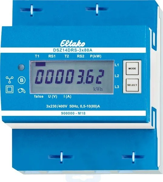
Eltako DSZ14DRS-3x80A Manual
PDF manual · 2 Pages
English



Quick check
Incorrect answer, please try again.
Chat with your Eltako DSZ14DRS-3x80A manual using AI
Get instant AI answers from your Eltako DSZ14DRS-3x80A manual
Ask anything about the Eltako DSZ14DRS-3x80A. Answers come from this manual, with the pages they are based on.
Ask a Question
Do you recommend DSZ14DRS-3x80A?
Yes NoFrequently Asked Questions
The unit supports a maximum current of 80 Amperes per phase. It handles single, double, or three-phase conductor configurations up to this limit safely within specified tolerance bands.
Is this answer helpful?
Yes, it stores data locally in non-volatile memory. While it transmits periodically to buses and networks, core functions do not rely on constant online access for basic metering tasks.
Is this answer helpful?
It uses the measured current lines for power but maintains very low consumption. Active power usage per path is not metered to ensure accurate calculation of load totals for clients.
Is this answer helpful?
PC tools like PCT14 help read detailed data including serial numbers and tariff readings. Initial address assignment usually involves the FAM14 handheld configuration tool for wireless pairing.
Is this answer helpful?
The display shows an error message indicating 'false' along with the specific phase conductor affected. This helps technicians quickly identify wiring faults during routine inspections.
Is this answer helpful?
Pressing the SELECT button activates the background lighting briefly. Pressing it longer reveals the device address or navigates deeper menu options for configuration changes.
Is this answer helpful?
Only qualified skilled electricians should perform installation. Improper handling creates fire or shock hazards and violates safety standards regarding high-voltage electrical systems.
Is this answer helpful?
Advantages and Disadvantages
Advantages

- Low standby power consumption reduces overall system load significantly
- Non-volatile memory retains historical data during power failures
- Compatible with wireless building automation networks via gateway modules
- Double tariff switching capability facilitates complex billing scenarios
- Clear error messaging on display assists quick troubleshooting
Disadvantages

- Requires specialized Eltako communication gateways for wireless operation
- Professional installation certified by skilled electricians is mandatory
- Limited conductor cross-section maximums restrict large gauge cables
- Operating temperature ceiling may limit use in extreme climates
- Address assignment needs specific tool interaction for initial setup
Product Specification
Type
Sensor
Standard
RS485
Function
Current measurement function
Topology
Bus
Features
IP51, Display
Product Description
Understanding the Eltako DSZ14DRS-3x80A Energy Management Solution
The Eltako DSZ14DRS-3x80A Bus-Funk-Drehstromzähler represents a sophisticated entry into the realm of three-phase energy monitoring. Designed specifically for modern electrical distribution systems, this device offers high precision and reliable data collection within compact enclosures. Electricians frequently choose this unit for its ability to integrate seamlessly into DIN-EN 60715 TH35 rails commonly found in industrial cabinets. Its modular form factor occupies only four TE units, conserving valuable panel space while maintaining robust connectivity options.
Technical Performance and Efficiency
Performance metrics are critical for energy audits, and this meter excels with Class B accuracy allowing only a one percent deviation. It handles maximum continuous currents up to eighty amperes across one, two, or three phase conductors efficiently. Standby consumption is remarkably low, drawing just zero point eight watts on L1 and half a watt on L2 and L3 paths individually. This minimizes self-measurement errors and contributes to overall grid efficiency targets set by facility managers worldwide.
Connectivity and Smart Integration
Integration into larger building networks distinguishes this technology. Via the RS485 interface, devices link using two-wire shielded cables typically utilized for telephone connections. Through the FAM14 module, readings transmit over wireless networks for remote monitoring applications. Consumptions values persist in non-volatile memory, ensuring no data loss occurs during unexpected power interruptions. The seven-segment LCD display remains readable for approximately two weeks after disconnecting supply voltage aids maintenance personnel during outages.
Operational Flexibility and Safety
Configuration supports double-tariff operations by applying specific voltages to designated terminals E1 and E2. Navigation through menus utilizes simple buttons labeled MODE and SELECT located directly next to the display unit. Error detection indicates issues such as missing phase conductors or reversed current directions visually on screen. Installation mandates skilled electrician involvement to mitigate risks associated with high voltage environments. Torque specifications for screw terminals must be respected to prevent mechanical damage during wiring procedures.
Maintenance and Environmental Adaptability
Operational temperature ranges span from negative twenty-five degrees Celsius up to positive fifty-five degrees Celsius depending on location. Storage conditions tolerate higher peaks reaching seventy degrees Celsius temporarily. Relative humidity levels should generally stay under seventy-five percent annually for optimal longevity. Protective sealing caps allow terminal compartments to remain secure against dust ingress when mounted correctly inside IP51 rated cabinets. Regular firmware updates via PC tools ensure continued compatibility with evolving control systems used in smart home infrastructures globally.
Search for 67,706 Manuals online


Type-in Brand or Model