
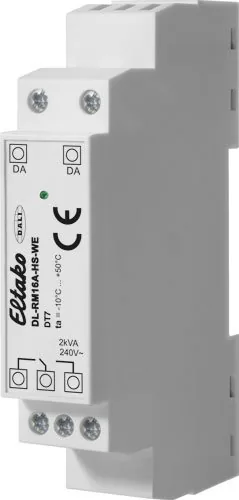

Eltako DL-RM16A-HS-WE Manual
PDF manual · 1 Pages
English


Quick check
Incorrect answer, please try again.
Chat with your Eltako DL-RM16A-HS-WE manual using AI
Get instant AI answers from your Eltako DL-RM16A-HS-WE manual
Ask anything about the Eltako DL-RM16A-HS-WE. Answers come from this manual, with the pages they are based on.
Ask a Question
Do you recommend DL-RM16A-HS-WE?
Yes NoFrequently Asked Questions
The device is powered directly over the DALI bus with a consumption of twenty seven milliamps. There is no need for an additional external power supply unit as the module draws its operating voltage from the bus cable itself.
Is this answer helpful?
Yes, the DL-RM16A-HS-WE is a control device specifically designed for non-dimmable loads based on the DALI specifications for Device Type seven. It switches them on and off effectively.
Is this answer helpful?
This unit operates a single relay contact controlled over the DALI bus for DIN top-hat rails. It allows for the switching of loads connected to the twenty three zero volt mains.
Is this answer helpful?
Configuration is performed using dedicated DALI Cockpit PC software. Users connect the device via the interface to adjust settings like switching thresholds and power responses remotely.
Is this answer helpful?
Operating temperature ranges from negative twenty degrees Celsius up to positive fifty degrees Celsius at the mounting location. Storage temperatures can extend from minus twenty five to seventy degrees Celsius.
Is this answer helpful?
Yes, the relay features zero passage switch-on which prevents electrical transients and protects connected lamps during startup cycles.
Is this answer helpful?
Advantages and Disadvantages
Advantages

- Powered directly from the DALI bus eliminating the need for separate power supplies.
- Compact design measuring ninety eight millimeters fits standard DIN top hat rails easily.
- Adjustable response settings for bus power failure and initial power-on states.
- Integrated current limit protection handles surges greater than one hundred amps safely.
Disadvantages

- Requires skilled electricians for installation due to high voltage risks involved.
- Protection class IP20 limits usage in wet or dusty outdoor environments.
- Configuration requires specific PC software tools accessible only via USB connection.
- Maximum conductor size limited to two point five square millimeters for connections.
Product Specification
Type
Actuator
Function
Relay
Topology
Bus
Dimensions
0.69x3.86x2.20in
Features
IP20
Product Description
Advanced Building Automation Overview
Modern electrical systems require precise switching components to manage energy efficiently across large networks. The Eltako DL-RM16A-HS-WE serves this purpose effectively by integrating directly into DALI bus architectures designed for intelligent lighting control solutions. Professionals frequently consult technical resources like the Eltako DL-RM16A-HS-WE DALI Relay Module, Switch Actuator Manual to understand implementation details fully. This device controls relay contacts specifically tailored for DIN top hat rail installations following EN standards.
Its compact footprint measures approximately ninety eight millimeters wide making it space efficient for distribution boards. Power draw remains minimal at twenty seven milliamps since the unit draws energy straight from the communication bus eliminating external transformer requirements entirely. This design reduces clutter and simplifies cable management significantly during construction phases.
Operational Specifications
Reliability is paramount for commercial projects where downtime impacts revenue streams negatively. The module supports a maximum connected current rating of sixteen amps ensuring heavy loads can operate safely under supervision. Users appreciate the adjustable characteristics regarding power-up sequences and how the device reacts when bus power fails unexpectedly. Factory settings default to maintaining power state but engineers can override this behavior remotely through configuration tools compatible with PC software interfaces.
Integration involves connecting standard screw terminals accepting conductors up to two point five square millimeters thickness without stripping issues. Temperature resilience extends from negative twenty degrees Celsius to positive fifty degrees Celsius for active zones allowing deployment in unheated industrial environments comfortably. Humidity tolerance averages below seventy five percent annually ensuring longevity without corrosion risks over time.
Configuration and Safety Protocols
Setup procedures utilize virtual dim levels compared against distinct switching thresholds defined in international specifications. This logic determines exactly when the relay engages or disengages based on incoming commands received via the interface acting as a unique bus user address. Installation mandates completion by qualified electricians only to prevent potential hazards including fire or severe electric shock accidents.
Careful attention to storage conditions between minus twenty five and seventy degrees Celsius preserves component integrity before initial activation occurs. Always retain relevant manuals for future troubleshooting scenarios requiring specific command set knowledge regarding fading delays and dimming speeds implemented locally. Proper disposal of associated waste containers follows environmental regulations strictly prohibiting mixing with household refuse materials.
The interface represents a bus user and is therefore addressable allowing for granular control schemes. Loads without input capability are easily integrated into existing loops using this actuator node. Commands enable on or off states instantly without delay unless programmed otherwise via fade time parameters.
Critical Maintenance Reminders
Regular checks ensure continued compliance with updated firmware releases available online. Zero passage switching protects connected lamps from inrush currents exceeding one hundred amps during start cycles preventing premature failure rates. Monitoring voltage fluctuations helps detect early signs of bus interference before total system collapse occurs. Consultation with support teams clarifies ambiguous points regarding Device Type seven functions found within the product specification sheets. Adherence to these guidelines guarantees optimal performance throughout the expected operational lifespan of the equipment purchased originally.
Search for 67,706 Manuals online


Type-in Brand or Model