
Eltako BGW14 Manual
PDF manual · 1 Pages
English


Quick check
Incorrect answer, please try again.
Chat with your Eltako BGW14 manual using AI
Get instant AI answers from your Eltako BGW14 manual
Ask anything about the Eltako BGW14. Answers come from this manual, with the pages they are based on.
Ask a Question
Do you recommend BGW14?
Yes NoFrequently Asked Questions
A single BGW14 gateway unit supports up to sixteen individual sensors connected to the bus terminals.
Is this answer helpful?
The standby loss is limited to zero point three watt, ensuring high energy efficiency during operation.
Is this answer helpful?
Standard telephone wire is sufficient, specifically J-Y ST Y 2x2x0 point eight mm squared equivalents.
Is this answer helpful?
Turn the rotary switch to the right stop and rotate back five times within ten seconds.
Is this answer helpful?
Operating temperature is minus twenty to plus fifty degrees Celsius, while storage allows minus twenty-five to plus seventy degrees.
Is this answer helpful?
Advantages and Disadvantages
Advantages

- Extremely low standby power consumption at only zero point three watt for energy savings
- Supports long cable runs up to one thousand meters for flexible installation
- Modular DIN rail design saves space and fits standard electrical panels easily
- Scalable architecture allows up to eight devices for 128 total sensor support
Disadvantages

- Requires skilled electrician for safe installation to avoid fire or shock hazards
- Configuration complexity arises when addressing multiple devices on the same bus
- Ambient temperature limit restricts usage in very high heat environments
Product Specification
Type
Hardware Control Unit
Standard
RS485
Function
Gateway
Topology
Bus
Features
IP20
Product Description
Introduction
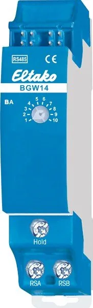
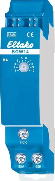
Integration begins by referencing the Eltako BGW14 RS485-Bus Gateway 1TE REG Manual guidelines for optimal setup procedures. This device acts as a vital intermediary link, facilitating bidirectional communication between wireless sensors and the standardized RS485 bus infrastructure used in industrial and residential settings. Its modular construction allows for easy mounting directly onto a standard TH35 DIN rail within electrical enclosures. The design prioritizes energy efficiency with a standby power loss of merely zero point three watt, reducing overall operational costs significantly over long deployment periods. Technical support contacts are available in German and English regions for additional assistance whenever complex issues arise during the commissioning phase.
Specifications and Connections
Connectivity extends to support a variety of specific sensor types including BUTH55ED, BBH55E, BTR55EH, and BT-F55E units. Each gateway unit can manage up to sixteen individual sensors connected via the RSA and RSB terminals. Data transmission and simultaneous power supply utilize a four-wire bus architecture powered by a twelve-volt DC source. Installers can use standard telephone wires for connecting leads, which simplifies material sourcing. Maximum permissible line lengths reach one thousand meters, providing ample coverage for large facilities. Proper termination using 120 ohm resistors at the extremities is required to ensure signal quality across the network segment. This configuration ensures data packets travel reliably without degradation over distance.
Advanced Features
The system employs a cyclic query mechanism where the gateway constantly polls all linked sensors for updated readings. Transmitted telegrams are compared against previous records to minimize redundant data traffic on the bus. Status updates occur every five minutes for recurring data loops. This intelligent management reduces bandwidth utilization significantly during periods of inactivity. Users can enter transmitting wireless IDs for individual BUTH sensors within the configuration area starting from version eight point eleven. Clear all functions reset both wireless identities and internal addresses upon command. Eight turns clears everything entirely to factory default settings. Specifications listed in the Eltako BGW14 RS485-Bus Gateway 1TE REG Manual data suggests using GBA14 housing for easier maintenance access during routine service intervals. Green LED indicator lights continuously when a connection is set up with PCT14. It flashes briefly when data output occurs on the RS485 bus interface. Operating mode rotary switch BA positions range from one to eight for unique identification. Temperature tolerance spans from minus twenty degrees Celsius up to fifty degrees Celsius. Storage conditions allow a wider range between negative twenty-five and positive seventy degrees Celsius. Annual average relative humidity must not exceed seventy-five percent for consistent performance over time.
Search for 67,706 Manuals online


Type-in Brand or Model