Manual.ly Logo

Doepke DRCBO 3 B16/0,03/1N-A KV Manual

0.0 · 0 Ratings

PDF manual · 2 Pages

English

M: OA-GPT-5-NAN
page

/ 2

Loading...
c9f06ce21aee682737fbff5b49efc42adfd7 page 1
Schaltbild
1N
2N
Datenblatt
Produktbezeichnung DRCBO 3 DRCBO 3 KV DRCBO 3 F
Fehlerstrom -
auslösecharakteristik
Typ A / Typ AC Typ A Typ F
Polanordnung 
Stoßstromfestigkeit  
kurzzeitverzögert

nein ja
Bemessungsfrequenz 
Bemessungsstoß-
spannungsfestigkeit

Kurzschluss -
vorsicherung SCPD gG


Bemessungs-
schaltvermögen

Anzugsdrehmoment 
 
Materialstärke


Maße 
 
Lagertemperatur 
Produktnorm 




Montage- und Bedienungsanleitung
für Fehlerstromschutzschalter mit eingebautem
Überstromauslöser der Baureihe DRCBO 3
 -

von Geräten dieser Art nicht für den elektrotechnischen Laien geeignet.
       

-
zuklären.
Anwendungs- und Warnhinweise
        

 
      

 
   

        
     

           

Bestimmungsgemäßer Gebrauch und Montage
Schutzschaltgeräte der Baureihe DRCBO 3 sind Fehlerstromschutzschalter mit

         


-

        




Installationshinweise
Die Montage erfolgt durch Aufschnappen auf die Tragschiene. Der Anschluss ist



Prüfungen und Funktionskontrolle
-
          

           
            
         -
 -

       


Gewährleistung
          


       



Installation and Operating Manual
for residual current circuit-breaker with integrated
overcurrent protection of the DRCBO 3 series
         -
cal specialists. The installation of devices of this type is not appro-
        
    
             
          
protective device.
Application instructions and warnings
 
          
corrosive gases in order to preserve the correct tripping function in the long term.

 
          


or selective devices and surge protection measures and system optimisations can
provide a remedy.
 -

Intended use and mounting
          
         
     


        


the associated device covers.
             


Installation notes
           
             


Testing and functional check
             
           
               
              
           

             




the location.
Warranty
  
           
      
-



Wiring diagram
1N
2N
Datasheet
Product description DRCBO 3 DRCBO 3 KV DRCBO 3 F
Residual current trip
characteristic
Type A / Type AC Type A Type F
Terminal position 
Surge current strength  
Short-time delayed

no yes
Rated frequency 
Rated surge voltage
capacity


fuse SCPD gG



capacity

Tightening torque 
Clamping area 
Material thickness


Dimensions 
 
Storage temperature 
Product standard 




Doepke Doepke

|

|
 
|

|

DE EN CZ SKDE EN CZ SK

Chat with your Doepke DRCBO 3 B16/0,03/1N-A KV manual using AI

Get instant AI answers from your Doepke DRCBO 3 B16/0,03/1N-A KV manual

Ask anything about the Doepke DRCBO 3 B16/0,03/1N-A KV. Answers come from this manual, with the pages they are based on.

DRCBO 3 B16/0,03/1N-A KV Maintenance Schedule

Remind me when maintenance is due
Semiannual
Test the RCBO using the test button

Under normal operating conditions, press test button T and verify that the RCBO trips. The toggle must move to zero and the tripped display must appear blue.

Every working day
Test the RCBO in non-stationary systems

For non-stationary systems, press test button T each working day and verify that the RCBO trips.

Free maintenance reminders

Timed to your purchase date. Always free, unsubscribe anytime.

By submitting you agree to the privacy policy. Unsubscribe with one click in any email.
M: gpt-5.6-terra

Ask a Question

0/1000

Do you recommend DRCBO 3 B16/0,03/1N-A KV?

Yes No

Frequently Asked Questions

A

It is a combined residual-current device and miniature circuit breaker (DRCBO) with 16 A B-curve overcurrent protection and 30 mA residual-current sensitivity, designed to protect circuits against earth-faults and overloads in one compact unit.

Is this answer helpful?

A

The DRCBO 3 family offers Type A, Type AC and Type F residual-current characteristics to accommodate a variety of connected equipment and nonlinear loads requiring different detection behaviours.

Is this answer helpful?

A

No. The manual emphasises professional installation by a qualified electrician to ensure correct wiring, torque settings and compliance with local electrical standards; improper installation risks ineffective protection or hazards.

Is this answer helpful?

A

Perform the built-in test-button check periodically as recommended by the manufacturer or local regulations. Keep the device clean, avoid corrosive atmospheres, and verify connections and torque during inspections to ensure continued reliable operation.

Is this answer helpful?

A

It is suitable for general-purpose circuits, lighting and socket circuits in residences and small commercial installations where 30 mA protection and 16 A rated current match the circuit requirements.

Is this answer helpful?

A

No integrated surge protection is provided; surge mitigation or selective coordination may require additional devices or system design to achieve selective tripping and handle transient overvoltages.

Is this answer helpful?

A

Store and operate the unit within specified temperature ranges and avoid corrosive gases which can impair tripping performance. Follow the manual’s storage and ambient guidance to preserve long-term reliability.

Is this answer helpful?

M: OA-GPT-5-NAN

Advantages and Disadvantages

Advantages

  • Space-saving combination of RCD and MCB reduces panel complexity.
  • 30 mA sensitivity protects people while limiting nuisance tripping.
  • Available residual-current types (A/AC/F) for varied load compatibility.
  • DIN-rail mounting and clear terminals speed professional installation.
  • Built-in test function enables easy periodic verification.
VS

Disadvantages

  • Requires qualified electrician for correct installation and testing.
  • May need additional selective protection for complex systems.
  • Performance can degrade in corrosive atmospheres if not protected.
  • Fixed 16 A B-characteristic limits current applications without alternatives.
  • Surge or special fault conditions may require external measures.
M: OA-GPT-5-NAN

Product Specification

Type

RCBO

Number of poles

1 + N

Rated voltage

230V

Rated current

16A

Rated residual current

30mA

Residual current type

A

Tripping characteristic

B

Degree of protection

IP20

Width

1.42 in

Number of modules

2

Special features

short-time delayed

M: OA-GPT-54-NAN

Product Description

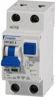
Doepke FI-/LS-Kombinationen DRCBO 3 B16/0,03/1N-A KV Manual

The Doepke DRCBO 3 B16/0,03/1N-A KV is a compact residual-current circuit breaker with integrated overcurrent protection designed for modern electrical installations. Combining earth-leakage detection (RCD) and short-circuit/overcurrent protection (MCB) in one unit, it simplifies distribution boards while ensuring reliable protection for circuits in homes, small commercial spaces and specialized installations.

This model features a 16 A B-type overcurrent tripping characteristic and a 30 mA residual current sensitivity, tailored to provide good nuisance-resistance while protecting people from electric shock and reducing fire risk from earth-fault currents. The DRCBO 3 family includes variants with Type A, Type AC and Type F residual-current characteristics, making them adaptable to circuits with different appliance profiles and electronic loads.

Key practical features include DIN-rail mounting for fast installation, clearly marked terminals for safe wiring, and mechanical test functions to regularly verify the tripping mechanism. The device supports rated frequency and surge conditions common in distribution systems and is compatible with appropriate short-circuit protection fuses (SCPD gG) and wiring practices. Compact dimensions and standardised mounting make the unit easy to fit into existing consumer units or new panels during upgrades.

Safety and correct operation depend on professional installation and adherence to the specified wiring diagrams and torque settings. The manual emphasises that the device is not for layman installation, outlines testing and functional checks, and includes environmental guidance such as recommended storage temperature and avoidance of corrosive atmospheres to preserve long-term trip performance. Periodic testing after installation ensures continued protection and compliance with local regulations.

For installers and specifiers, the DRCBO 3 B16/0,03/1N-A KV presents a cost-effective way to combine two protective functions into one compact module, reducing wiring complexity and saving panel space. It is suited for general circuits, lighting, and many socket circuits where 30 mA protection is required. Variants with short-time delay or different residual-current types allow tailoring to selective or sensitive loads.

Notes:

  • Always follow manufacturer torque values and wiring diagrams when connecting.
  • Perform regular test-button checks to confirm residual-current operation.
  • Choose the appropriate residual type (A/AC/F) for connected appliances.
  • Keep units away from corrosive gases and within storage/operating temperature ranges.

Pros and Cons Summary

Pros:

  • Space-saving RCD+MCB combination for simplified distribution boards.
  • 30 mA sensitivity balances human protection and nuisance immunity.
  • DIN-rail mounting and clear terminal markers speed installation.
  • Multiple residual-current types (A/AC/F) for diverse applications.
  • Integrated test function supports periodic verification.

Cons:

  • Requires a qualified electrician for correct installation and testing.
  • May not suit highly selective coordination needs without system design.
  • Corrosive environments can shorten reliable service life.
  • Limited to rated current and characteristic (16 A, B) — needs correct selection.
  • External measures may be needed for surge or complex fault scenarios.

3–5 Most Important Results

  1. Combines RCD and MCB in a single compact module for panel space savings and simpler wiring.
  2. 16 A B-curve with 30 mA residual sensitivity offers balanced protection against overloads and earth faults.
  3. Available in Type A/AC/F variants to match different equipment and nonlinear loads.
  4. DIN-rail mounting and clear terminals enable fast, standardised installation in consumer units.
  5. Manual stresses professional installation, periodic testing, and environmental care for reliable operation.
M: OA-GPT-5-NAN

© Copyright 2026 Manual.ly