Manual.ly Logo

Doepke DFS 4 125 Manual

0.0 · 0 Ratings

PDF manual · 2 Pages

English

M: OA-GPT-5-NAN
page

/ 2

Loading...
8433110423a6137528e1a3ee47f3379713af page 2
type A residual currents is guaranteed. If this is the case, it should be checked rst
if there is operating voltage of min. 50 V AC between two active conductors. If this
voltage is present at the switch and the LED does not illuminate, the residual current
circuit-breaker must be replaced.
Insulation test
The insulation test should be carried out using test devices according to
DIN EN 61557-2. To carry out a simple insulation test for the electrical system, we
recommend supplying power ‘from above’ for type-B switches. This means only
the switch needs to be switched oduring the test and the measurement can take
place on the system side. Performing an insulation test when the residual cur-
rent circuit-breaker is switched on or on the side with the odd-numbered termi-
nals can lead to erroneous measurement values as a result of the internal adaptor.
In this case, we recommend disconnecting the switch for the duration of the test.
Exception:
An insulation test of up to 1000 V can also be carried out on the upper odd terminals
without the need to disconnect beforehand for all AC-DC sensitive residual current
circuit-breakers in the ISO HD ‘ISΩ HD’ design.
Important information on operating an AC-DC sensitive residual current circuit-
breaker (DFS 2/4 B/B+) with electronic equipment
(such as frequency converters, inverters etc.)
1. Electronic equipment and its associated EMC protective provisions,
such as integrated or in series-connected EMC lters, as well as shielded cables,
can produce high capacitive leakage currents.
2. The maximum number of items of electronic equipment connected
down stream of the DFS 2 B/DFS 4 B is based on the level of leakage currents that
occur. Excessive leakage currents may lead to undesired tripping. Relevant infor-
mation concerning the leakage currents that are produced can be requested from
the manufacturers of the electronic equipment.
3. During operation with frequency converters, long, shielded motor cables can re-
sult in high leakage currents, which may lead to undesired tripping. If necessary,
a sinusoidal output lter should be connected to the frequency converter output
terminals (before the shielded motor cable).
4. When switching electrical systems with electronic equipment on and o,
it is possible that very high surge leakage currents will be produced, which will
lead to tripping should they continue for the relevant duration. The switch-on and
switch-o operations should be kept as short as possible. Quick-switching, all-
pole contactors or switches with stored energy operating mechanisms are suit-
able (manual rotary switches should not be used).
5. According to the instructions, a 3-conductor EMC lter should only be connected
in series with the relevant electronic equipment. To avoid impairing the lter ef-
fect, under no circumstances should further single-phase consumers such as in-
candescent bulbs be connected on the output side of the EMC lter.
6. As a rule, dierent clock frequencies (chopper) can be selected in the case of
electronic equipment. In the worst-case scenario, the clock frequency may lead
to a tendency to oscillation in an upstream EMC lter and therefore to greatly
increased leakage currents, which then cause the DFS 2/4 B to trip. In this case,
the clock frequency must be changed.
7. Frequency converters with an integrated EMC lter often only allow a maximum
shielded motor cable length of 5 to 10 m. Longer cable lengths lead to greatly
increased leakage currents and can render the integrated EMC lter ineective.
The manufacturer's specications must always be observed for the frequency
converter.
Guarantee
All professionally installed, unaltered devices are covered by warranty during the
statutory guarantee period from the day of purchase by the end user. The guarantee
does not apply to damage incurred during transport or caused by short-circuit, over-
loading or improper use. For defects in workmanship or material that are discovered
within the warranty period, the company will provide repair or replacement free of
charge. The warranty will be rendered null and void if the device is opened without
authorisation.
Wiring diagrams
2 4
1 3
~
1/N 7/N3 5
8/N
2/N
4 6
~
S two-pole (grey: type B only) S four-pole, neutral on left or right,
depending on device version
(grey: type B only)
Installation and operating instructions
for residual current circuit-breakers
of series DFS 2 and DFS 4
These installation and operating instructions are aimed at qualied
electrical specialists. The installation of devices of this type is not ap
-
propriate for electrical laypersons due to the considerable potential
dangers. These installation and operating instructions must be re
-
tained, so that they can be referred to at a later stage. The operator of
the electrical installation must be informed about the use and function
of this protective device.
Application instructions and warnings
The following notes and warnings must be observed in order to ensure safe opera-
tion:
1. Devices with visible damage must not be installed or used.
2. Operation must only occur under normal ambient conditions free of corrosive
gases in order to preserve the correct tripping function in the long term. Cor
-
rosive gases are chlorine, ammonia and sulphurous air, for example. Residual
current circuit-breakers with "HD" specication are recommended for environ
-
ments aected by corrosive gases.
3. The user must be made aware of regular function testing using the test key T.
4. The function test with the test key is not a substitute for regular testing of the
electrical system.
5. Erroneous tripping due to operation related leakage currents or atmos-
pheric interference cannot be ruled out with absolute certainty. The conse-
quences must be considered and countermeasures taken where necessary.
Selective residual current circuit-breakers as well as surge protection measures
and system optimisations can provide a remedy.
6. If the RCCB cannot be switched on, or if the consumer network is not connected,
the device must be replaced.
7. Disposal is subject to the statutory regulations of the European Union (WEEE/
German Electrical and Electronic Equipment Act).
For further information and data sheets, please visit www.doepke.de and search by
the article number or scan the QR code on the front of the housing.
Intended use:
DFS 2 and DFS 4 series protective devices are residual current circuit-breakers
without integrated overcurrent protection. They provide protection through auto-
matic switch-oin electrical systems, e.g. in accordance with VDE 0100 part 410.
They meet the requirements for residual current protection in accordance with their
characteristics on the name plate. The switch-o function can be tested using a
push-button which is also accessible to laypersons. Regular testing can also increase
the endurance of the circuit-breaker, as the mechanism of the latch is moved when
tripped in addition to the electrical test.
Electrical connection and installation:
The electrical connection must be as shown in the wiring diagram and must comply
with the terminal designation on the device. With type-B devices, it is preferable for the
power to be supplied to the odd-numbered terminals (simplied insulation measure-
ment). If the device is to be operated without using all poles, it is essential (in order to
ensure the connection is correct) to observe the position of the test key as per the wir-
ing diagram and the operating voltage range of the test circuit in accordance with the
data sheet. DFS 4 devices have an N-left design as standard. N-right devices have an
‘R’ in their designation. Scrape and grease aluminium conductors immediately before
connection. The device must be installed on a mounting rail (TS 35) according to
DIN EN 60715 in distribution boards that must ensure protection against direct con-
tact (which may be required depending on the location of use) and protection against
environmental inuences.
Testing and functional check
A simple function test with the assistance of test key T should be carried out after
the mains voltage and the circuit-breaker are switched on. When the key is pressed,
the DFS 2/DFS 4 must disconnect without delay; the toggle will then be in the centre
position. Resetting to position ‘1’ is only possible if the toggle has rst been moved
down to position ‘0’. The operation indicator beneath the toggle indicates the status
of the contacts: red = closed, green = open. This test must be carried out at least
every six months where the device is used as intended and must be repeated every
working day for non-stationary systems according to the regulation. If tripping does
not occur, the device must be replaced immediately. The operator must be informed
of this. All additional tests are covered by the prescribed acceptance test. Tests
should be carried out according to DGUV Regulation 3 (BGV A3) depending on the
location of use.
The green LED on the front of the housing of the DFS 2 B/DFS 4 B AC-DC sensitive
residual current circuit-breaker indicates that the AC-DC sensitive residual current
detection is active. If the LED does not illuminate, then only tripping in the event of
Doepke
3930298
|
02/2020
|
Doepke Schaltgeräte GmbH, Stellmacherstraße 11, D-26506 Norden
DE EN

Chat with your Doepke DFS 4 125 manual using AI

Get instant AI answers from your Doepke DFS 4 125 manual

Ask anything about the Doepke DFS 4 125. Answers come from this manual, with the pages they are based on.

DFS 4 125 Maintenance Schedule

Remind me when maintenance is due
Every six months
Test residual current circuit-breaker function

Press test key T to verify device disconnects without delay. Replace immediately if tripping does not occur.

Every working day
Test non-stationary system devices

Repeat function test with test key T every working day for non-stationary systems according to regulations.

Free maintenance reminders

Timed to your purchase date. Always free, unsubscribe anytime.

By submitting you agree to the privacy policy. Unsubscribe with one click in any email.
M: QW-35-FL

Ask a Question

0/1000

Do you recommend DFS 4 125?

Yes No

Frequently Asked Questions

A

AC/DC-sensitive means the device detects both alternating residual currents and pulsating DC fault currents, making it suitable for systems with frequency converters, inverters, and other electronic loads that can create non-sinusoidal leakage currents.

Is this answer helpful?

A

Under normal stationary use, perform the functional test at least every six months. For non-stationary or regulated installations, tests may be required daily or per local regulations. If the device fails to trip during the test, it must be replaced immediately.

Is this answer helpful?

A

For standard devices, insulation tests should follow DIN EN 61557-2 and may require disconnecting the device to avoid erroneous readings. Some ISO HD variants allow insulation testing up to 1000 V on specified terminals without prior disconnection.

Is this answer helpful?

A

Electronic equipment and EMC measures (filters, shielded cables) can produce high capacitive or surge leakage currents. Excessive leakage or unfavorable EMC filter interactions can cause nuisance tripping; mitigating steps include changing filter settings, using sinus output filters, or reducing cable lengths.

Is this answer helpful?

A

No. The DFS 4 125 is a residual current protective device without integrated overcurrent protection and must be installed together with appropriate overcurrent devices according to system design and standards.

Is this answer helpful?

A

First check that a minimum operating voltage (about 50 V AC) is present between active conductors. If voltage is present and the LED remains off, the device should be replaced as AC/DC-sensitive detection may be inactive.

Is this answer helpful?

A

Yes. Aluminium conductors should be scraped and greased immediately before connection to ensure reliable contact and prevent oxidation-related connection issues.

Is this answer helpful?

M: OA-GPT-5-NAN

Advantages and Disadvantages

Advantages

  • AC/DC-sensitive detection suitable for installations with electronic drives and inverters.
  • Clear status indication and accessible test push-button for regular functional checks.
  • Design allows simplified insulation testing when supplied to odd-numbered terminals (Type B).
VS

Disadvantages

  • Susceptible to nuisance tripping from high leakage currents generated by EMC filters or long shielded cables.
  • Does not include overcurrent protection; requires coordination with upstream devices.
  • Requires qualified installation and regular testing; not suitable for layperson installation.
M: OA-GPT-5-NAN

Product Specification

Type

RCCB

Number of poles

3 + N

Rated voltage

400V

Rated current

125A

Degree of protection

IP20

Width

2.83 in

Modular units

4

M: OA-GPT-54-NAN

Product Description

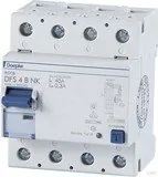
Doepke DFS 4 125 — Reliable AC/DC-Sensitive Residual Current Protection

The Doepke DFS 4 125 is a robust AC/DC-sensitive residual current circuit-breaker (RCCB) designed for demanding installations where reliable fault current detection and safe automatic disconnection are essential. Built for professional electrical use, the DFS 4 series provides sensitive detection of both AC and pulsating DC faults and integrates features that simplify testing, installation, and maintenance in industrial and commercial environments.

Key features and practical use

The DFS 4 125 supports all-pole and multi-pole installations, with clear terminal designation and wiring diagrams to ensure correct connections. Type B versions (AC/DC-sensitive) are recommended where electronic loads such as frequency converters and inverters are present. The device offers a visible status indicator under the toggle (red = closed, green = open) and an accessible test push-button that enables easy functional checks. For simplified insulation testing the preferred supply is to the odd-numbered terminals on Type B devices, reducing the need to disconnect downstream circuits.

Installation is intended for qualified electrical professionals and the breaker mounts on standard TS 35 DIN rails. Aluminium conductors should be scraped and greased before connection. The product is specified for environments free of corrosive gases; an HD variant is available for aggressive atmospheres. The device does not include overcurrent protection and must be combined with appropriate upstream overcurrent devices according to system requirements.

Interaction with electronic equipment

When used with electronic loads (frequency converters, inverters, EMC filters, shielded motor cables), the DFS 4 125 requires attention to leakage currents and EMC measures. Integrated or external EMC filters and long shielded cables can create capacitive leakage currents that may cause nuisance tripping. Measures include limiting downstream electronic devices to those specified by leakage current ratings, using sinus filters at frequency converter outputs, observing maximum shielded cable lengths (typically 5–10 m for converters with integrated EMC filters), and selecting appropriate switching devices to minimize long surge leakage during power-up.

Testing, maintenance, and warranty

Routine functional tests via the test key are recommended at least every six months (more frequently for non-stationary installations). If the device fails to trip during testing or cannot be switched on, it must be replaced. Insulation testing should follow DIN EN 61557-2 and, for certain ISO HD variants, insulation tests up to 1000 V can be done without disconnecting. The product includes a standard statutory warranty for professionally installed, unaltered devices; unauthorized opening voids the warranty.

Notes

  • Intended for qualified electrical installers only.
  • Do not use visibly damaged units; replace immediately if defective.
  • Observe manufacturer specs for EMC filters and frequency converter cabling.
M: OA-GPT-5-NAN

© Copyright 2026 Manual.ly