Manual.ly Logo

Doepke DFS 4 040 Manual

0.0 · 0 Ratings

PDF manual · 2 Pages

English

M: OA-GPT-5-NAN
page

/ 2

Loading...
5c56e6c866b742dfed660ac836afe6763a8e page 2
between two active conductors. If this voltage is present at the switch and the LED
does not illuminate, the residual current circuit-breaker must be replaced.
Insulation test
The insulation test should be carried out using test devices according to
DIN EN 61557-2. To carry out a simple insulation test for the electrical system, we
recommend supplying power ‘from above’. This means only the switch needs to be

Performing an insulation test when the residual current circuit-breaker is switched on
or on the side with the odd-numbered terminals can lead to erroneous measurement
values as a result of the internal adaptor. In this case, we recommend disconnecting
the switch for the duration of the test.
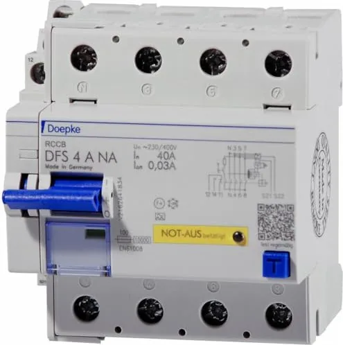
Emergency switch equipment function (NA added)
The emergency switch is connected at terminals S 21 and S 22. The emergency switch

event of wire breakage. The emergency switch equipment is ready as soon as the sup-
ply voltage is applied and the green LED ‘DC detection mode’ lights up. If the emer-
gency switch circuit is open, the red LED for ‘EMERGENCY SWITCH engaged’ lights
up, and the RCCB trips and cannot be switched on. If multiple DFS 4 EV NA devices
need to be operated via an emergency switch circuit, terminals S 21 and S 22 of the
devices must be connected in parallel. If several emergency switches are to be oper-
ated on one DFS 4 EV NA, the emergency switches should be connected in series.
Emergency switch equipment troubleshooting
If the red LED for ‘EMERGENCY SWITCH engaged’ lights up continuously even
though the emergency switch equipment has been reset, either there is a wire break-
-
ic cause of the fault, proceed as follows: Switch the supply voltage of the residual cur-

If the red LED continues to light up after the supply voltage is reconnected, the RCCB
is faulty. If the red LED no longer lights up, the cause of the fault lies in the system.
Warranty
All professionally installed, unaltered devices are covered by warranty for the dura-
tion of the statutory warranty period from the day of purchase by the end user. The
warranty does not apply to damage incurred during transport or caused by short-
circuit, overloading or improper use. Should any defects in workmanship or mate-
rial be discovered within the warranty period, the company will provide repair or
replacement free of charge. The warranty will be rendered null and void if the device
is opened without authorisation.
Wiring diagram
5 N
6 N
5 N
12 14 11 6 N
S 21 S 22
S DFS 2 A/F EV S DFS 2 A/F EV NA
1(N)
3
5
7(N)
2(N)
4
6
1(N)
3
5
7(N)
2(N)
4
6
8(N)
12
14
11
S 21 S 22
S DFS 4 A/F EV S DFS 4 A/F EV NA, neutral conductor left or right,
depending on the device version
S 21
S 22
S Connection of several DFS 4 EV NAs via an emergency switch circuit
with several switches
Installation and operating instructions
for two-/four-pole residual current circuit-breakers
in model ranges DFS 4 A EV, DFS 4 F EV
and DFS 4 A EV NA, DFS 4 F EV NA
    
electrical specialists. The installation of devices of this type is not ap-
propriate for electrical laypersons due to the considerable potential
dangers. These installation and operating instructions must be re-
tained, so that they can be referred to at a later stage. The operator of
the electrical installation must be informed about the use and function
of this protective device.
Application instructions and warnings
 Devices with visible damage must not be installed or used.
           
gases in order to preserve the correct tripping function in the long term. Corrosive
gases include chlorine, ammonia and sulphurous air, for example. Residual cur-


 The user must be made aware of regular function testing using the test button T.
 The function test with the test button is not a substitute for regular testing of the
electrical system.
 Erroneous tripping due to operational leakage currents or atmospheric interfer-
ence cannot be ruled out with absolute certainty. The consequences must be con-
sidered and countermeasures taken where necessary. Selective residual current
circuit-breakers as well as surge protection measures and system optimisations
can provide a remedy.
 If the residual current circuit-breaker cannot be switched on, or if the consumer
network is not connected, the device must be replaced.
       
German Electrical and Electronic Equipment Act).
For further information and data sheets, please visit www.doepke.de/en/ and search
by the article number or scan the QR code on the front of the housing.
Intended use
Residual direct current devices of series DFS 4 A EV/DFS 4 F EV, also known as
RDC-PDs, meet fault protection and protection against electric shock requirements,
in line with VDE 0100-722 in particular. An active additional device implemented in a
type A residual current circuit-breaker ensures the highest possible availability. It is
used to protect the normal operation of the residual current circuit-breaker during a
residual direct current equal to or larger than 6 mA and thus meets the requirements
of an RDC-PD as per IEC 62955.
          
function can be tested using a push-button which is also accessible to laypersons.
A regular test can increase the endurance of the circuit-breaker as the mechanism is
moved when tripped.
Electrical connection and installation
The device must be installed on a mounting rail (TS 35) according to DIN EN 60715 in
distribution boards that have to ensure protection against direct contact (which may
be required depending on the location of use) and protection against environmental
        
must comply with the terminal designation on the device. It is preferable to use the

device is to be operated without using all poles, it is essential (in order to ensure the
connection is correct) to observe the position of the test button as per the wiring
diagram and the operating voltage range of the test circuit in accordance with the
data sheet. DFS 4 devices have an N-left design as standard. N-right devices have a
‘R’ in their designation. Scrape and grease aluminium conductors immediately be-
fore connection.
Testing and functional check
A simple function test with the assistance of test button T should be carried out af-
ter the mains voltage and the circuit-breaker are switched on. When the button is
pressed, the DFS 4 A EV must disconnect without delay; the toggle will then be in the

moved down to position ‘0’. The operation indicator beneath the toggle indicates the
status of the contacts: red = closed, green = open. This test must be carried out at
least every six months where the device is used as intended and must be repeated
every working day for non-stationary systems according to the regulation. If tripping
does not occur, the device must be replaced immediately. The operator must be in-
formed of this. All additional tests are covered by the prescribed acceptance test.
           
on the location of use. The green LED on the front of the housing of the DFS 4 A EV
indicates that the 6-mA DC residual current detection is active. If the LED does not
illuminate, then only tripping in the event of type A residual currents is guaranteed. If

Doepke

|

|

DE EN

Chat with your Doepke DFS 4 040 manual using AI

Get instant AI answers from your Doepke DFS 4 040 manual

Ask anything about the Doepke DFS 4 040. Answers come from this manual, with the pages they are based on.

DFS 4 040 Maintenance Schedule

Remind me when maintenance is due
Daily
Test non-stationary system breaker

For non-stationary systems, repeat the test every working day according to regulations.

Semiannual
Test residual current circuit-breaker function

Press test button T at least every six months. If tripping does not occur, replace the device immediately.

Free maintenance reminders

Timed to your purchase date. Always free, unsubscribe anytime.

By submitting you agree to the privacy policy. Unsubscribe with one click in any email.
M: QW-35-FL

Ask a Question

0/1000

Do you recommend DFS 4 040?

Yes No

Frequently Asked Questions

A

The DFS 4 040 is a four‑pole residual current circuit‑breaker designed to detect AC and DC residual currents and disconnect supply automatically to protect people and equipment in installations where mixed fault currents may occur.

Is this answer helpful?

A

No. Due to potential danger and the need for correct upstream/downstream RCD coordination and wiring, installation and commissioning must be carried out by a qualified electrical professional.

Is this answer helpful?

A

Perform a function test using the built‑in test button at least every six months for stationary installations. For non‑stationary or mobile setups, test daily. If the device fails to trip during testing, it must be replaced immediately.

Is this answer helpful?

A

The green LED signals the presence of the internal operating voltage required for AC/DC (type A and B) sensing. If the LED is off only type A detection is guaranteed; the MI device may lose full all‑current detection capability.

Is this answer helpful?

A

No. During insulation tests according to DIN EN 61557‑2 the RCCB must be switched off, because the internal auxiliary supply can distort measurements on terminals 1, 3, 5 and 7.

Is this answer helpful?

A

No. The DFS 4 series are residual current devices without integrated overcurrent protection. Appropriate external overcurrent protective devices (OCPD/SCPD) must be provided as required by the installation.

Is this answer helpful?

A

Yes. Operation is limited to normal ambient conditions free of corrosive gases (e.g., chlorine, ammonia, sulphur gases). Exposure to such atmospheres can impair long‑term tripping performance.

Is this answer helpful?

M: OA-GPT-5-NAN

Advantages and Disadvantages

Advantages

  • All‑current sensitivity (AC and DC) in MI variant allows detection of mixed fault currents.
  • DIN‑rail modular design for easy integration in distribution boards (TS 35).
  • Accessible test button and LED status indicator simplify routine functional checks.
  • Flexible wiring: neutral can be placed left or right; supply recommended on terminals 1,3,5,7.
  • Low DC trip threshold in MI variant protects upstream type A devices from DC faults.
VS

Disadvantages

  • No built‑in overcurrent protection; requires correct external OCPD selection.
  • Installation and servicing must be performed by qualified electricians only.
  • Sensitive to corrosive gases — unsuitable for harsh chemical environments.
  • Pulsating or smooth DC can lower effective trip thresholds and cause unexpected behavior.
  • Must be switched off during insulation tests to avoid distorted measurements.
M: OA-GPT-5-NAN

Product Specification

Type

RCCB

Number of Poles

3 + N

Rated Voltage

400V

Rated Current

40A

Degree of Protection

IP20

Width

2.83 in

Modular Units

4

M: OA-GPT-54-NAN

Product Description

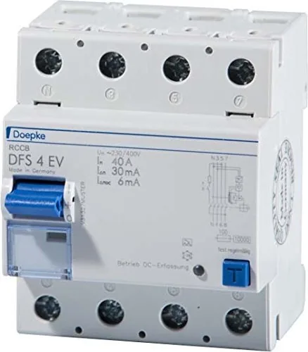
Doepke DFS 4 040 — Reliable all‑current residual current protection

The Doepke DFS 4 040 is a four‑pole residual current circuit‑breaker (RCCB) designed to provide dependable protection in installations where AC and DC fault currents may occur. Built as a DIN‑rail modular device for TS 35, the DFS 4 040 combines sensitive all‑current detection with practical installation and maintenance features. Its MI variant offers particularly low DC tripping thresholds, making it suitable where DC components or downstream equipment can produce DC leakage currents that would otherwise defeat standard type A protection.

Compact yet robust, the DFS 4 040 supports flexible wiring with neutral conductor on either side and recommended supply connections at terminals 1, 3, 5 and 7. It is intended to be used in conjunction with appropriate overcurrent protection devices (it has no built‑in overcurrent protection) and must be installed by qualified electricians due to potential hazards. The unit includes a user‑accessible test button for routine functional checks and an LED status indicator that signals whether the internal power for AC/DC sensing is present.

Key practical points include regular testing (at least every six months for stationary systems and daily for mobile or non‑fixed installations), adherence to environment limits (free of corrosive gases), and clear guidance on downstream/upstream combinations of RCD types to avoid nuisance or missed tripping. When the green LED is lit the device senses both type A and B residual currents; if it is dark, only type A tripping is guaranteed.

Because the DFS 4 040 is sensitive to DC residual currents, special attention must be paid to pulsating DC (type A) and smooth DC faults — these can produce lower effective trip thresholds than rated values. For insulation testing (DIN EN 61557‑2), the device should be switched off or isolated as measurements on the terminals can be distorted by the internal auxiliary supply.

Overall, the Doepke DFS 4 040 is aimed at installations requiring robust detection of mixed AC/DC fault currents, with built‑in features to support safe operation and maintenance when properly installed and tested.

Notes

  • Install and service only by qualified personnel. Ensure protection against corrosive atmospheres.
  • Perform functional tests regularly using the accessible test button; replace immediately if tests fail.
  • For insulation tests, switch the device off to avoid erroneous readings at terminals 1, 3, 5, 7.
  • Use correct upstream/downstream RCD combinations as recommended to avoid unwanted interactions.
M: OA-GPT-5-NAN

© Copyright 2026 Manual.ly