Manual.ly Logo

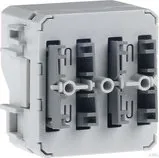
Berker W.1 Manual

0.0 · 0 Ratings

PDF manual · 2 Pages

English

M: QW-35-FL
page

/ 2

Loading...
85b637637af8ed89e1b48eb4a0fd2b0c30d9 page 2
Berker GmbH & Co. KG - Klagebach 38 - 58579 Schalksmühle/Germany - Telefon: + 49 (0) 23 55/90 5-0 - Telefax: + 49 (0) 23 55/90 5-111 - www.berker.com - 6LE002667A - 12/2016
Accessories
W.1 Cover for xgang
push-button module 613076354x, 30xx 35 xx
W.1 frame xgang horizontal 13xx 35 0x
W.1 frame xgang vertical 13xx 35 0x
W.1 Housing 1gang with
frame surface-mounted 61 1891 35 0x
W.1 Housing 2gang with
frame surface-mounted 67 193x 35 xx
W.1 Housing 3gang with
frame surface-mounted 60 1930 35 0x
Warranty
We reserve the right to realise technical and formal
changes to the product in the interest of technical
progress.
Our products are under guarantee within the scope
of the statutory provisions.
If you have a warranty claim, please contact the
point of sale.
Safety instructions z
Electrical equipment may only be installed and
assembled by a qualifi ed electrician. Always fol-
low the relevant accident prevention regulations
of the country.
Failure to comply with these installation in-
structions may result in damage to the device,
fi re or other hazards.
When installing and routing cables, always
comply with the applicable regulations and
standards for SELV electrical circuits.
These instructions are an integral component
of the product and must be retained by the end
user.
Design and layout of the device
(1)
(1)
(2)
Figure 1: Front view of push-button module
(3)
(4)
Figure 2: Rear view of push-button module
(1) Status LED, push-button module 2gang
(2) Status LED, push-button module 1gang
(3) Programming button and red programming
LED
(4) KNX bus connection terminal
Function
System information
This device is a product of the KNX system and
corresponds to the KNX guidelines. Detailed
specialised knowledge obtained from KNX training
courses
is required for understanding. The planning, instal-
lation and commissioning are carried out with the
help of KNX-certifi ed software.
Commissioning system link
The function of the device is software-depend-
ent. The software is to be taken from the product
database. You can fi nd the latest version of the
product database, technical descriptions as well as
conversion and additional support programmes on
our website.
Commissioning easy link
The function of the device is confi guration-depend-
ent. The confi guration can also be done using
devices developed specially for simple setting and
commissioning.
This type of confi guration is only possible with devices
of the easy link system. easy link stands for easy, visual-
ly supported commissioning. Preconfi gured standard
functions are assigned to the in/outputs by means of a
service module.
Correct use
- Operation of loads, e.g. light on/off, dimming,
blind up/down, saving and opening light scenes,
etc.
- Surface-mounted/fl ush-mounted installation,
splash-protected
- Installation into wall box according to DIN
49073
Product characteristics
- Commissioning and programming in S-mode
and E-mode
- Push-button functions: switching/dimming, blind
control, value transmitter, scene call-up, specifi -
cation of the heating operating mode, priority
- Red status LED per push-button
Operation
The functions of the buttons, their operation and
the activation of the loads can be adjusted individu-
allay for each device.
There are two operating modes:
- Single-surface operation:
Lighting is switched on/off and dimmed/bright-
ened by repeatedly pressing a push-button
operation area.
- Two-surface operation:
Two superimposed push-button operation areas
form a function pair. For example, pressing the
top surface switches/dims lighting on/makes it
brighter, pressing the bottom surface switches it
off/makes it darker.
Operating a function or load
Loads, such as lighting, blinds, etc., are operated
using the push-button operation areas, which are
dependent on the device confi guration/program-
ming.
Press one push-button operation area.
The underlying function is executed.
The actuation pulse lasts for the duration of the
actuation. Depending on the function, short and
long touches can trigger different actions, e.g.
switching/dimming.
Information for electricians
Installation and electrical connection
DANGER!
Touching live parts in the installation
environment can result in an electric
shock!
An electric shock can be lethal!
Disconnect the connecting cables
before working on the device and cover
all live parts in the area!
ç
Connecting and installing the device
Surface-mounted installation (Figure 4):
Install lower housing (9) in correct position.
Route bus cable though sealing membrane and
into housing.
Connect bus cable (red +/black -).
Insert push-button module (8) into lower housing
(9) until fastening brackets engage.
Mount sealing piece (6) and upper housing (7) on
lower housing (9). To do this, fasten quick-release
bayonet connectors in lower housing using a
screwdriver and applying a 1/4 turn clockwise.
Attach touch cover (5) to push-button module.
Dismantling
Remove touch cover (5) from push-button
module (8).
Remove sealing piece (6) and upper housing
(7). To do this, unlock quick-release bayonet
connectors using a screwdriver and applying a
1/4 turn anticlockwise.
Remove push-button module (8).
OR:
Flush-mounted installation (Figure 5):
Route bus cable out of wall box (11) and connect
(red +/black -).
Place push-button module (8) onto fl ush-mount-
ed frame (10) until fastening brackets engage.
Fasten fl ush-mounted frame (10) in the correct
position on wall box (11) using fi tting screws.
Mount sealing piece (6) on fl ush-mounted frame.
To do this, fasten quick-release bayonet connec-
tors in fl ush-mounted frame using a screwdriver
and applying a 1/4 turn clockwise.
Attach touch cover (5) to push-button module.
Dismantling
Remove touch cover (5) from push-button
module (8).
Dismantle sealing piece (6).
Dismantle fl ush-mounted frame (10).
Remove push-button module (8) from
fl ush-mounted frame.
Commissioning
system link - Loading the physical address and
application software
The physical address is only ever assigned
for one device. Only one device can ever be in
programming mode.
It is advisable to programme the physical ad-
dress before installation.
Dismantle touch cover (5), sealing piece (6) and
upper housing (7).
Remove push-button module (8) from lower
housing (9) or from wall box.
Switch on bus voltage
Press programming button (3).
The programming LED (3) lights up.
If the programming LED does not light up, no
bus voltage is present.
Load the physical address and application
software into the device.
The programming LED goes out.
Note down the physical address on the labelling
fi eld.
The loading of non-compatible application
software is indicated by fl ashing of the status
LED(s) (1/2).
Reassemble device (see Connecting and
installing the device).
easy link
Information on the system confi guration can be
taken from the extensive description of the service
module easy link.
Appendix
Technical data
KNX medium TP 1
Commissioning mode S-mode, E-controller
Current consumption KNX DC 21 … 32 V SELV
Current consumption KNX typ. 10 mA
Power consumption typ. 150 mW
Connection mode KNX bus connecting terminals
Degree of protection IP 55
Protection class III
Operating temperature -40 … +30 °C
Storage/transport temperature -50 … +50 °C
Standards EN 60669-2-1; EN 60669-1
EN 50428
Troubleshooting
Bus operation is not possible.
Cause: Bus voltage is not present.
Check bus connection terminals for correct
polarity.
Check bus voltage by briefl y pressing the
programming button (3); red programming LED (3)
lights up if bus voltage is present.
Figure 4: Installing the device with a surface-mounted housing
(5) Touch cover 1gang (not included in scope of delivery)
(6) Sealing piece (not included in scope of delivery)
(7) Upper housing (not included in scope of delivery)
(8) Push-button module
(9) Surface-mounted upper housing (not included in scope of delivery)
(10) Frame 1gang for fl ush-mounted installation (not included in scope of delivery)
(11) Flush-mounted wall box (not included in scope of delivery)
(5)
(6)
(7)
(8)
(9)
(5)
(6)
(10)
(8)
(11)
Figure 5: Installing the device into a wall box

Chat with your Berker W.1 manual using AI

Get instant AI answers from your Berker W.1 manual

Ask anything about the Berker W.1. Answers come from this manual, with the pages they are based on.

Ask a Question

0/1000

Do you recommend W.1?

Yes No

Frequently Asked Questions

A

Yes, commissioning requires KNX-certified software for system link or easy link setup to define addresses and functions correctly.

Is this answer helpful?

A

No, installation must be performed by a qualified electrician following safety regulations to avoid electric shock hazards.

Is this answer helpful?

A

The device operates on a nominal DC voltage of 21 to 32 volts SELV, ensuring safe low-voltage operation.

Is this answer helpful?

A

Yes, it supports switching and dimming functions depending on the configuration assigned via the programming software.

Is this answer helpful?

A

It has an IP55 rating, protecting against dust and water jets, making it suitable for splash-protected indoor areas.

Is this answer helpful?

A

It meets EN 60669-2-1, EN 60669-1, and EN 50428 standards for safety and product quality assurance.

Is this answer helpful?

A

The device supports both surface-mounted and flush-mounted installation options according to DIN 49073 specifications.

Is this answer helpful?

M: QW-35-FL

Advantages and Disadvantages

Advantages

  • Integrated KNX bus coupler eliminates external adapters
  • High IP55 protection rating for durability
  • Supports single-surface and two-surface operation
  • Wide operating temperature range for flexibility
  • Compliant with EN 50428 and EN 60669 standards
VS

Disadvantages

  • Requires qualified electrician for installation
  • Some frames and covers sold separately
  • Programming requires specific software tools
M: QW-35-FL

Product Specification

Type

Sensor

Standard

KNX

Function

Pushbutton, Blind control, Dimming function

Topology

Bus

Dimensions

1.73x1.73x0.87in

Features

IP20

M: QW-35-FL

Product Description

Revolutionize Your Smart Home with Berker W.1

Smart home technology relies heavily on reliable interfaces between humans and their automated environments. The Berker W.1 Switch with Bus Connector stands out as a premier choice for modern installations. This 1-gang device integrates seamlessly into KNX systems, offering robust control for lighting and other electrical loads. Whether you are managing a single room or an entire building, this rocker switch provides the incline setting preferred by many designers. It creates a bridge between physical interaction and digital control logic. It provides smooth operation.

Seamless KNX Integration

The core advantage lies in its built-in bus coupler. This feature eliminates the need for external adapters, streamlining the installation process significantly. Electricians appreciate the standardized KNX TP 1 medium support which ensures interoperability. It operates on a DC voltage between 21 and 32 volts, ensuring safety and compatibility with standard low-voltage infrastructure. The device functions within a wide temperature range, making it suitable for various indoor environments without thermal stress issues. Heat management is excellent.

Flexible Operation Modes

Users benefit from multiple operation modes designed for convenience. The system supports both single-surface and two-surface operation types effectively. In single-surface mode, you can toggle lighting or dim brightness by repeatedly pressing the area. Two-surface configurations allow paired functions, such as turning lights on or off using distinct touch areas. The red status LED provides immediate visual feedback on the button state to confirm actions clearly.

Installation Simplicity

Installation versatility is another key highlight for any project. The unit supports both surface-mounted and flush-mounted options according to DIN 49073 standards. Security precautions are paramount, requiring qualified personnel for electrical setup to prevent hazards. The sealed housing offers an IP55 protection rating, safeguarding against dust and water jets during use. Commissioning is facilitated through easy link or system link software, allowing quick configuration of physical addresses and application logic easily.

Future-Ready Design

Maintaining these devices is straightforward with modular components available today. Covers and frames allow for aesthetic customization to match any decor style. The product database ensures access to the latest application software for updates. With compliance to EN 50428 and EN 60669 standards, safety and reliability remain top priorities for users. Furthermore, the device supports scene recall and heating mode specifications for advanced needs. This versatility allows for complex automation scenarios without additional hardware costs. Accessories like housings and frames enable tailored looks for any room. Regular updates ensure system security. Proper mounting ensures longevity and maintains the IP55 seal integrity. Remember to follow all safety instructions regarding SELV circuits strictly. This investment guarantees a smart, efficient future for your home automation projects.

M: QW-35-FL

© Copyright 2026 Manual.ly