
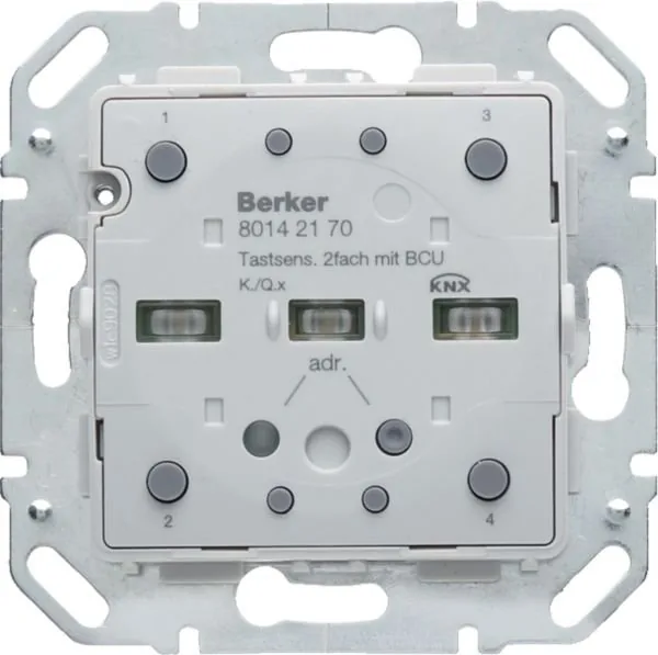

Berker Q.x 8014 21 Manual
PDF manual · 2 Pages
English



Quick check
Incorrect answer, please try again.
Chat with your Berker Q.x 8014 21 manual using AI
Get instant AI answers from your Berker Q.x 8014 21 manual
Ask anything about the Berker Q.x 8014 21. Answers come from this manual, with the pages they are based on.
Ask a Question
Do you recommend Q.x 8014 21?
Yes NoFrequently Asked Questions
Yes, electrical equipment may only be installed by a qualified electrician following accident prevention regulations to avoid damage or hazards.
Is this answer helpful?
It is a product of the KNX system and corresponds to KNX guidelines requiring specialized knowledge from training courses.
Is this answer helpful?
Yes, push-button functions include switching and dimming, along with blind control and scene call-up capabilities.
Is this answer helpful?
No, the touch cover and frame are not within the scope of delivery but must be assembled separately.
Is this answer helpful?
The size is 71 x 71 x 32 mm with an assembly height of 11 mm from the supporting ring.
Is this answer helpful?
Use the programming button after switching on bus voltage, then load the address and application software.
Is this answer helpful?
The rated voltage is KNX DC 21 through 32 V SELV for normal operation and communication.
Is this answer helpful?
Advantages and Disadvantages
Advantages

- KNX system compatibility allows broad integration with existing automation setups
- Configurable status LEDs provide clear visual feedback to users instantly
- Supports multiple operating modes for flexible user control scenarios
- Integrated bus coupler simplifies wiring architecture within the wall box
- Compatible with standard DIN wall box installations for seamless fitting
Disadvantages

- Qualified electrician required for safe installation and setup procedures
- Touch cover often sold separately as an optional accessory item
- Software dependent for function assignment tasks during initial config
- Needs specific knx certification for programming and debugging tasks
- Bus voltage checks necessary for troubleshooting connection issues regularly
Product Specification
Type
Sensor
Standard
KNX
Function
Control, Shutter Control, Dimming, Temperature
Topology
Bus
Dimensions
2.80 x 2.80 x 1.65 in
Features
IP20
Product Description
Elevating Living Spaces with Smart Touch Technology
Introduction to Advanced Building Automation
In the rapidly evolving landscape of residential technology, having a reliable interface is crucial for modern comfort. The Berker Q.x Touch Sensor Module 2-Way, with integrated bus coupler Manual provides essential guidance for installing this sophisticated device. This module stands out as a premium solution for managing lighting and blind systems within a global KNX network. It brings a sleek aesthetic combined with robust functionality to any standard electrical installation found in contemporary homes.
Seamless Touch Control Experience for Everyone
One of the standout features of this device is its versatile touch surface operation capabilities. Users can engage in single-surface operation for simple switching tasks or utilize two-surface operation for more nuanced control scenarios. For instance, one touch might turn a light on while another dims it darker simultaneously. This flexibility allows customization to fit specific lifestyle preferences and family habits. The status LEDs offer visual confirmation of your commands clearly, and their colors can be configured to match your specific interior decor needs perfectly for a unified look.
Installation and Compatibility Considerations for Pros
While the technology is advanced, proper setup is key for safety and performance. Electrical equipment should always be handled by a qualified professional to prevent serious hazards during work. The module fits into standard DIN wall boxes using a supporting ring with prong connection securely. It is important to note that the touch cover is not always included in the base scope of delivery explicitly. Planning and commissioning rely on KNX certified software tools which simplify the system link start-up process significantly. Alternatively, easy link start-up offers visually supported configuration using a dedicated service module.
Why Choose This Reliable Hardware Solution
Adopting this module means investing in long-term reliability and energy efficiency standards globally. With a current consumption of typ. 10 mA on KNX DC bus, it remains extremely economical for daily use over time. The operating temperature range supports diverse indoor environments effectively without any significant issues arising. Troubleshooting is straightforward if you check bus voltage presence first during diagnosis sessions. Ultimately, this hardware bridges the gap between traditional wiring methods and modern smart living demands seamlessly today for all users. Always retain these details as they remain integral components of the product throughout its entire lifecycle for future reference.
Safety First During Every Phase
Safety regulations dictate that SELV circuits must be followed strictly when laying cables in walls. Protect the device from pollution like dust or paint paste during renovation work phases completely. Failure to comply may result in fire hazards or damage to the device itself permanently. These warnings ensure that the system operates safely under all conditions provided by the manufacturer guidelines consistently.
Technical Specifications Overview
The dimensions are compact at 71 x 71 x 32 mm fitting standard frames easily inside cavities. Protection class III and IP20 rating ensure durability against common household elements encountered daily. It supports EN60669 standards which guarantees compliance with European safety norms generally accepted across the market reliably.
Search for 67,706 Manuals online


Type-in Brand or Model