product database, technical descriptions as well as
conversion and additional support programmes on
our website.
easy link start-up
The function of the device is conguration-de-
pendent. The conguration can also be done using
devices developed specially for simple setting and
start-up.
This type of conguration is only possible with devices
of the easy link system. easy link stands for easy,
visually supported start-up. Precongured standard
functions are assigned to the in/outputs by means of a
service module.
Correct use
-Single room temperature control in KNX instal-
lations
-Installation into wall box according to DIN 49073
-Auxiliary voltage supply according to EN 61558
or in the context of the specications (see Tech-
nical data)
Product characteristics
-Start-up and programming in S-mode and E-mode
-Measurement of the room temperature and
comparison with set temperature
-Touch-sensitive control surface
-Setpoint specication by selecting the operating
mode
-Operating modes comfort, standby, economy
mode, frost/heat protected, holiday mode
-Heating and cooling mode
-Ventilation function
-Timer function
-Display of statuses and power consumption
-Push-button functions such as switching, dimming,
blind/roller shutter etc. (only KNX room controllers)
-Connection for external temperature sensor
(see Accessories)
Functional description
The device compares the current room temperature
with the set temperature and controls heating and
cooling devices according to the current requirements.
The heating system must also be suitable for
the heating or cooling mode.
The set temperature is dened by the operating
mode and can be changed via the menu operating
mode - holiday mode or settings. The selected op-
erating mode, current time and measured room tem-
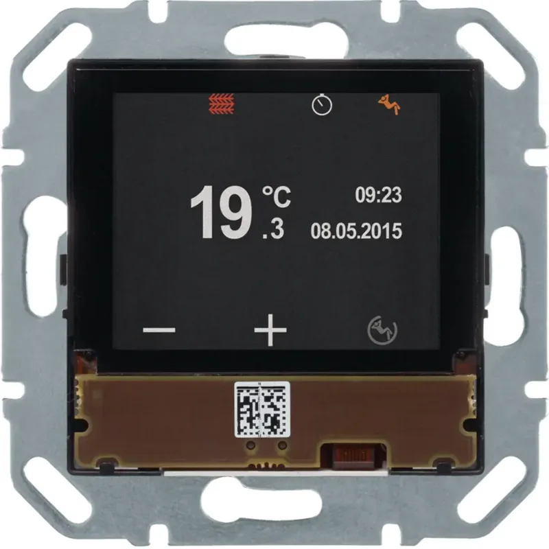
perature are indicated in the display as an example
(gure 3). The display contents can be represented
in dierent ways depending on the setting. The upper
status line symbolically represents the status of the
device currently set (6).
Room controller variant
The room controller also has push-button functions
in addition to the thermostat. This allows e.g. lighting
to be switched/dimmed or roller shutters/blinds to
be moved. This rst requires making settings in the
ETS or service-module easy link. Up to 3 control
surfaces can be freely congured for these functions
per display page. A maximum of 9 functions are
freely programmable.
Operation
Display elements and operating concept
The display is subdivided into a display area and
control surface. In the upper rows of the display (6)
only symbols indicate the set/active parameters in the
basic display. Below this e.g. the current room tem-
perature (7), current display of an external tempera-
ture sensor (11) and the current date or current time
(10) are visualised in basic operation. In the setting
mode, both areas are used for displaying possible
selection and parameter values.
The lower row of the display area (8) changes its dis-
play depending on the menu item. Symbols indicate
the active/inactive functions that can be triggered
using the touch control surface (9) below.
-Push button operation:
Switching on/o, conrming or changing a
function of a function parameter by pressing
the respective touch control surface below the
displayed symbols.
-Slider operation:
By "swiping" from left to right or right to left over
the touch-sensitive control surface it is possible
to switch to the next/previous page, exit the
current operating level or cancel the parameter
entry/change.
Operating a function or load
Loads, such as lighting or blinds, are operated
using the touch-sensitive control surface and is
dependent on the device conguration.
Press a touch control surface (9) below the
symbols (8).
The stored function is executed.
The actuation pulse lasts for the duration of the
actuation. Depending on the function, short and
long touches can trigger dierent actions, e.g.
switching/dimming.
Operation in the basic display
The following functions are active in the basic
display:
/ : Increase/decrease room temperature
setpoint.
The temperature can be varied between 7 ...
40°C for each operating mode.The display
changes to red when the heating energy is
supplied or to blue when cooled.
Extension of the comfort operating mode.
Display of comfort extension via
.
Or:
/ Change-over between comfort mode and
economy mode.
The functions for the basic display can be set
and congured individually in the ETS.
24.7
16:27
-
13.3°C
(6)
(7)
(8)
(9)
(10)
(11)
°C
Figure 3: Basic display
(6) Status line with symbols
(7) Current room temperature display
(8) Display of the active functions
(9) Touch-sensitive control surface
(10) Display of date/time
(11) Temperature display of the external tempera-
ture sensor
Setting the parameters and values
Change to the next/previous page by swiping
your nger over the touch control surface (9).
<<<<
<<<<
24
.7
16:27
-13.3°C
°C
Figure 4: Slider function
By "swiping" your nger over the touch-sensi-
tive control surface you cancel the parameter
setting on each menu level and change to the
next higher menu level.
P
P
Pressing one of the three touch areas (gure 5) be-
low the function symbols causes the corresponding
function to be executed.
24.7
16:27
-13.3°C
°C
Figure 5: Touch areas of the touch control surface
Menu Status - A1
The current state of the parameterised devices,
such as window contact request, status of the
connected loads, dewpoint operation, is displayed
in the menustatus. A symbol and the correspond-
ing value display with unit can be assigned to the
current status.
Home status
dew point active
window is open
Figure 6: Menu status
Menu
- A2
The
menu allows you to reset the
thermostat to one of the two last parameter settings
saved (gure 7).
If one of the last saved settings is selected, the
current parameters in the device will be overwritten
with the last settings saved.
No problem
Would you like to return
to your settings of
JJJJ/MM/DD
Figure 7: Menu
Settings menu - A3
In the settings menu, the basic functions and
parameters of the device are to be set/changed
manually.
Settings
setpoint heating
device info
setpoint cooling
Figure 8: Settings menu
Select the parameter with
/ .
Conrm the selection with
.
The selected parameter will open in a new
screen.
Setpoint heating:
Setting of the temperature setpoint for the operat-
ing modes Comfort, Standby and Night Reduction.
Setpoint cooling:
Setting of the temperature setpoint for the operat-
ing modes Comfort, Standby and Night Reduction.
Internal sensor:
Parameter for setting the temperature adjust-
ment with the temperature sensor in the device.
External sensor:
Parameter for setting the temperature adjust-
ment with an external temperature sensor.
Heating or cooling mode:
Settings
Heat/coo mode
External senssor
Date & Time
Figure 9: Heating or cooling mode selection
Press touch control surface under
.
The operating mode (gure 9) changes from
heating
to cooling .
In the function line (8) the inactive operating mode
is displayed on the right, which can be activated
using the control surface.
Date/time:
Date/time
time 10:45
date 24 / 04 / 2014
Figure 10: Date/time setting
Date and time are not set in the default state.
The respective value selected can be changed
(gure 10).
Increase/decrease numerical value with
/ .
Change to the next adjustable value with
.
At the last value to be set, the display changes
from
to .
Conrm the entry with
.
24
h
/12
h
Time format
24
12
h
Settings
time format
date & time
screen brightness
h
Figure 11: Time format setting
Press touch control surface under
12
h
for the
12
h
display.
The time format changes from the 24
h
to 12
h
display. In the function line (8) the
24
h
appears in
order to switch back again to 24
h
(gure 11).
Screen brightness:
Individual adjustment of the screen brightness
for operation. The display is not switched o
completely with at value 0%, residual bright
-
ness is always still present.
Screensaver:
Basic setting for the screensaver (brightness,
screensaver symbol).
Language:
Changeover of the display and menu language
to German, English, French,...
Programming mode:
Activation of the programming mode. The
device can be loaded with the physical address
and application software.
Reset:
Resetting to the factory settings. Afterwards, the
device must be reprogrammed and set.
Info:
Display of system information using the touch
control surface under , such as the manu-
facturer, software version, last ETS download
date and phys. address.
Timer menu - A4
In the timer menu you have to set on which weekdays
or sections of the week and at what times the operat-
ing modes Comfort, Standby or Economy mode (Night
Reduction) should be switched on and o.
Timer program
Monday-Friday
Saturday-Sunday
Monday-Sunday
Figure 12: Setting timer
Setting switching times for operating mode
change-over
Select a section of the week or weekday with
/ .
Conrm with
.(gure 12).
The display changes for setting the switching
time (gure 13).
The operating mode Economy (Night Reduction)
is selected automatically.
If necessary, change with
to select another
operating mode (gure 14).
Set the switch-on/switch-o time with
/
(gure 13).
00:00
Timer program
Figure 13: Setting the switching time
The operation should be repeated for additional
switching times.
Swipe your nger over the touch control surface.
The display returns to the Timer submenu. The
coloured circle next to the weekday or section of the
week changes colour. Weekdays or sections of the
week with the same coloured circle are congured
with the same timers.
Activating/deactivating timer
Timer program
Timer program
Monday
Monday-Sunday
Activating/deactivating the timer
Select the timer parameter with
/ .
Switch timer on/o using
/ .
If the timer is activated, the set programming
block is automatically executed once a week
recurrently. If the timer is deactivated, adjust-
ments to the temperature setpoint or operating
mode must be set manually.
Optimisation:
The KNX thermostat/room controller "learns" inde-
pendently which lead time is required to reach the
desired temperature.
Holiday mode menu - A5
In the holiday mode menu the set temperaturecan
lowered to an adjustable minimum temperature in
absence.
Vacation mode
Figure 15: Activating holiday mode
Activate the holiday mode with
.
The symbol changes to the display .
In the status line (6) of the basic display
indicates the holiday mode.
The display changes for setting the operating
mode for the holiday mode (gure 16).
Holiday mode
Figure 16: Selecting operating mode for holiday
mode
Select the desired operating mode for the peri-
od of absence.
The display additionally indicates the number of
days for the holiday mode.
1
Holiday mode
Number of days
OK
Figure 17: Setting duration of holiday mode
Increase/decrease the number of days of
absence with
/ .
Conrm the setting with OK
The holiday mode operating mode is activated
for the duration of the set days.
The display switches to the holiday mode
display (gure 17).
Deactivate the holiday mode prematurely with
the touch area.
In the status line (6) of the basic display the
symbol for the holiday mode disappears.
Or:
Conrm the entry with
.
Operating mode menu - A6
In the operating mode menu, you can select be-
tween three operating modes (gure 19):
Mode selection
Figure 18: Selecting operating mode
-Comfort
in presence
-Standby
in absence
-Economy (nighttime operation)
for the night re-
duction
Activate the desired mode using the touch
control surface.
In the status line (6) of the basic display the
symbol.
/ / indicates the respective
holiday mode.
Extractor fan menu- A7
In the extractor fan menu, extractor fan stages
from 0 ... 6 can be set.
2
a
Fan control
Figure19: Setting of the extractor fan stages
Increase/decrease the extractor fan stage with
touch control surface
/ .
The number in the extractor fan symbol indi-
cates the set stage.
Press touch control surface a.
The extractor fan function switches to automatic
operation.
The symbol a provides the option of returning
back to manual operation
.
s
å`
/2
%
Quick check
I'm not a robot
Incorrect answer, please try again.
Chat with your Berker KNX Thermostat 8044 01 00 manual using AI
Get instant AI answers from your Berker KNX Thermostat 8044 01 00 manual
Ask anything about the Berker KNX Thermostat 8044 01 00. Answers come from this manual, with the pages they are based on.
Ask a Question
0/1000
Do you recommend KNX Thermostat 8044 01 00?
YesNo
Frequently Asked
Questions
A
Yes, the manual states that electrical equipment must be installed by a qualified electrician following accident prevention regulations. Incorrect handling may cause fire hazards or device damage.
Is this answer helpful?
A
The device allows switching between heating and cooling modes. You can configure specific setpoints for both modes depending on the selected operating parameter settings in the menu.
Is this answer helpful?
A
Yes, there is a connecting terminal for an external temperature sensor. This allows you to measure conditions in critical areas rather than relying solely on the internal sensor.
Is this answer helpful?
A
Available modes include comfort, standby, economy mode, frost protected mode, and holiday mode. These can be automated via the timer menu or changed manually.
Is this answer helpful?
A
Activate holiday mode via the settings menu. You can select the operating mode and duration. The display will show a symbol indicating active holiday protection.
Is this answer helpful?
A
The device requires a 24 V SELV auxiliary voltage supply compliant with EN 61558 specifications. Only suitable power supplies listed in accessories should be used.
Is this answer helpful?
M: QW-35-FL
Advantagesand
Disadvantages
Advantages
Intuitive touch-sensitive control surface with slide and tap functions
Compatible with KNX standard systems for easy integration
Supports multiple operating modes including holiday and economy
High resolution display shows temperature and status clearly
External temperature sensor connection for improved accuracy
VS
Disadvantages
Requires qualified electrician for proper electrical installation
Specific 24 V auxiliary power supply is mandatory for operation
Setup requires knowledge of KNX software configuration tools
Sensitive components need protection from heat sources
Initial programming may be complex for inexperienced users
M: QW-35-FL
Product
Specification
Type
Control unit hardware, Sensor
Standard
KNX
Function
Temperature, Control
Special Features
IP21, IK04, Display
M: QW-35-FL
Product
Description
Revolutionizing Home Climate Control with Advanced Knx Technology
Welcome to the advanced world of smart home automation where genuine comfort meets supreme efficiency. The Berker KNX Thermostat with Display stands out as a premier solution for intelligent climate management in modern residential spaces. Designed for seamless integration into KNX installations, this device offers precise temperature regulation through intuitive touch controls and a bright digital interface. Whether you are upgrading an existing system or constructing a new smart home infrastructure, this unit provides a robust platform for managing heating and cooling needs effectively throughout every season of the year.
At the core of this technological innovation lies a high-resolution display paired with a highly sensitive control surface. Users can effortlessly adjust setpoints, switch between various operating modes such as comfort, economy, standby, and holiday, and monitor energy consumption directly on the front panel. The interface supports advanced swipe gestures and touch buttons, making navigation fluid and responsive for daily routine tasks. Unlike traditional thermostats, this device intelligently learns user patterns and optimizes heating cycles automatically to reduce unnecessary waste while maintaining your exact desired warmth levels consistently.
Proper installation is crucial for optimal performance. Professional electrical expertise is strongly recommended to ensure the safe connection of the KNX bus and the required auxiliary voltage supply. The device operates exclusively on SELV circuits and mandates a compatible 24 V power source to function correctly. Once connected, the system allows for extensive configuration using certified software tools and resources often referenced alongside the Berker KNX Thermostat with Display, UP Control Panel Manual guidelines. This flexibility enables users to program complex timers, link external temperature sensors, and even control lighting or roller shutters if utilizing the room controller variant capabilities.
Energy efficiency remains a primary benefit for eco-conscious homeowners wishing to save money. By utilizing multiple operating modes like night reduction and frost protection, users can significantly lower utility bills without sacrificing household comfort levels. The inclusion of an optional external temperature sensor refines measurement accuracy by analyzing conditions in critical zones rather than relying solely on internal readings. For extended absences, a dedicated holiday mode maintains safe minimum temperatures to prevent pipe damage during cold weather periods.
Routine maintenance is straightforward, featuring a convenient reset function and status monitoring menus that instantly alert users to potential issues like open window contacts or dew point risks. Language options allow full customization for diverse European markets ensuring usability everywhere. Detailed instructions guide users through setup and programming modes to guarantee reliable operation.
Optimization features allow the thermostat to learn lead times required to reach desired temperatures independently over time. Safety is always prioritized with warnings against installation near interference sources to ensure accurate measurements. This system represents a significant step forward in residential climate control, combining sleek aesthetic appeal with powerful functional capabilities using reliable KNX technology standards used worldwide.