
Berker KNX Flush-Mounted Bus Coupler Manual
PDF manual · 3 Pages
English



Quick check
Incorrect answer, please try again.
Chat with your Berker KNX Flush-Mounted Bus Coupler manual using AI
Get instant AI answers from your Berker KNX Flush-Mounted Bus Coupler manual
Ask anything about the Berker KNX Flush-Mounted Bus Coupler. Answers come from this manual, with the pages they are based on.
Ask a Question
Do you recommend KNX Flush-Mounted Bus Coupler?
Yes NoFrequently Asked Questions
It connects compatible flush-mounted application modules, such as operating or sensor elements, to a KNX TP1 automation system. It forms the concealed technical interface between the wall-mounted module and the KNX bus.
Is this answer helpful?
The coupler operates on KNX SELV voltage of 21 to 32 V DC. Correct SELV wiring practices and applicable installation standards must be observed during planning and installation.
Is this answer helpful?
Yes. It is designed for recessed mounting in a device box compliant with DIN 49073. The installation orientation should be observed, and a blank cover should be fitted if no application module is installed.
Is this answer helpful?
A qualified installer uses KNX-certified software to assign the physical address and download application software. Pressing the programming button activates the programming LED. Only one device should be in programming mode during address assignment.
Is this answer helpful?
The 7504 00 01 version provides up to 100 mW at the application interface and has a maximum consumption of 150 mW with a module. The 7504 00 03 version provides up to 150 mW and consumes up to 200 mW, supporting compatible B.IQ temperature-regulator use.
Is this answer helpful?
Installation and electrical connection should be performed by qualified electricians with KNX knowledge. Safe installation requires isolation from mains voltage, protection of nearby live parts, correct bus polarity, and appropriate software-based commissioning.
Is this answer helpful?
Advantages and Disadvantages
Advantages

- Flush-mounted design supports a neat, integrated KNX installation in standard device boxes.
- Compatible with KNX TP1 and S-Mode commissioning for established automation workflows.
- Programming button and LED provide straightforward physical address assignment.
- Two versions provide different interface power levels, including support for B.IQ temperature-regulator applications.
Disadvantages

- Installation, wiring, and commissioning require qualified electrical and KNX expertise.
- Functionality depends on the selected application module and installed software.
- The application interface must be handled carefully to avoid damage during module fitting.
- Operating temperature is limited to -5 to +45 degrees C, so it is not intended for extreme environments.
Product Specification
Type
Control unit hardware
Standard
KNX
Function
Gateway
Topology
Bus
Product Description
Berker KNX Bus Coupler UP Manual: A Practical Foundation for KNX Controls
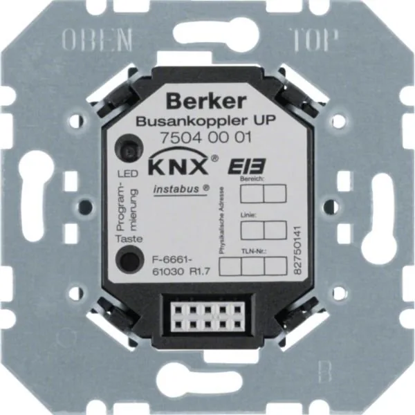
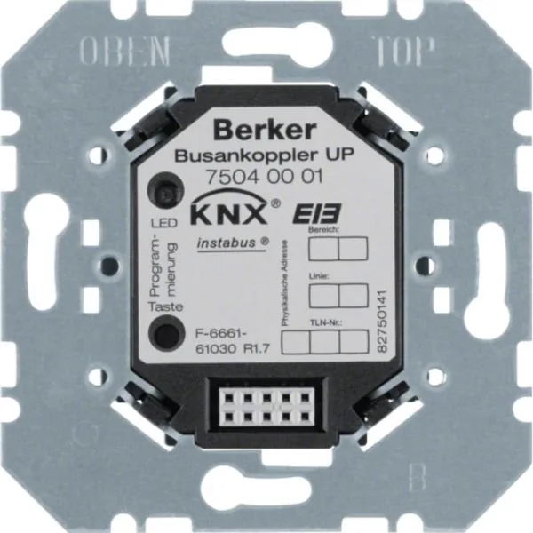
The Berker KNX Bus Coupler UP is a recessed installation component designed to connect compatible flush-mounted application modules to a KNX building automation system. For installers and system planners, the Berker KNX Bus Coupler UP Manual keyword represents an important reference point when selecting a reliable interface for switches, sensors, and other room-control elements in intelligent residential or commercial projects.
Designed for Flexible KNX Integration
This bus coupler is intended for installation in a standard device box in accordance with DIN 49073. It provides the link between the KNX TP1 bus and the attached application module, allowing the visible operating element to communicate with the wider automation network. Depending on the selected version, it can also support B.IQ applications with temperature control functionality.
The unit operates with KNX SELV voltage from 21 to 32 V DC and uses the KNX S-Mode commissioning method. Its compact recessed format helps create a clean installation while keeping the technical connection safely behind the wall-mounted control surface. The front-facing programming button and LED simplify addressing during setup, while the application interface and bus connection are located to support an orderly installation process.
Installation and Commissioning Considerations
Professional electrical installation is essential for safe use. The KNX bus cable is connected with the standard polarity arrangement: red for positive and black for negative. Before any work begins, the circuit must be isolated and nearby live parts protected. During renovation work, the coupler should also be shielded from paint, adhesive, dust, and other contaminants that could affect operation.
Commissioning is completed through KNX-certified software. The installer activates programming mode using the programming button, assigns a physical address, and then downloads the required application software. Only one device should be in programming mode while an address is assigned. Some application modules need to be attached before software is downloaded, so compatibility requirements should be checked for the specific control module in use.
Versions and Operating Limits
Berker offers two relevant variants. The 7504 00 01 version has a maximum KNX power consumption of 150 mW with an application module and supplies up to 100 mW through the application interface. The 7504 00 03 version supports up to 200 mW consumption and 150 mW output, making it suitable for compatible B.IQ temperature-regulator applications.
Both versions are built for indoor conditions, with an operating temperature range of -5 to +45 degrees C. Protection class III and SELV operation support their use in properly planned low-voltage KNX installations.
Note: Select the bus coupler according to the connected application module, required interface power, and the software functions planned for the KNX project.
Search for 67,706 Manuals online


Type-in Brand or Model