
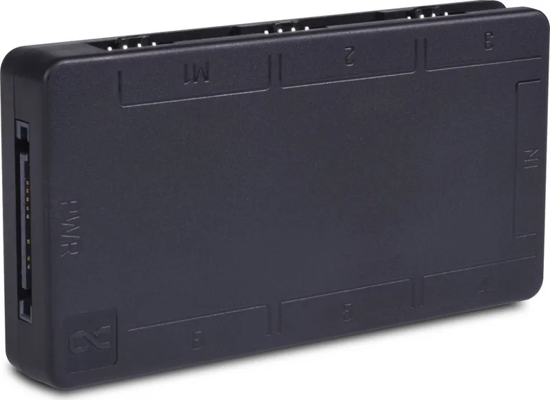
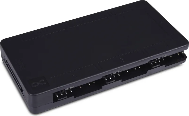
Alphacool Core 6x 4-Pin PWM/DRGB Splitter Manual
PDF manual · 2 Pages
English



Quick check
Incorrect answer, please try again.
Chat with your Alphacool Core 6x 4-Pin PWM/DRGB Splitter manual using AI
Get instant AI answers from your Alphacool Core 6x 4-Pin PWM/DRGB Splitter manual
Ask anything about the Alphacool Core 6x 4-Pin PWM/DRGB Splitter. Answers come from this manual, with the pages they are based on.
Ask a Question
Do you recommend Core 6x 4-Pin PWM/DRGB Splitter?
Yes NoFrequently Asked Questions
Use the included Velcro strips. Peel the film, stick it under the controller, then attach to the case.
Is this answer helpful?
A SATA power plug from the power supply is required.
Is this answer helpful?
No, you must use a 3-pin terminal on the motherboard to prevent damage.
Is this answer helpful?
The controller can draw up to 22.5 W (4.5 A).
Is this answer helpful?
Socket M1 is designated for the tacho signal and must be filled first.
Is this answer helpful?
Unplug the power cord from the wall socket to cut power.
Is this answer helpful?
It includes an aRGB mainboard cable and a 4-pin PWM cable.
Is this answer helpful?
Advantages and Disadvantages
Advantages

- Supports six connection points for PWM fans and RGB lighting
- Dedicated SATA power input prevents motherboard overload
- Includes Velcro mounting for secure and detachable installation
- Handles maximum power consumption of 22.5 W at 4.5 A
- Tacho signal monitoring via M1 socket for fan speed data
Disadvantages

- Motherboard ARGB output must be 3-pin to avoid damage
- Power supply must be unplugged before opening chassis
- Requires manual configuration of fan sockets and lighting
- M1 socket must be populated first for tacho signal
- Limited to 22.5W total power draw across all ports
Product Specification
Type
Regulated fan hub, light control
Form Factor
Internal
Fans
6
Channels
1 (Speed), 6 (Lighting, 6x RGB-Out 3-Pin ARGB Header, +5V/DATA/GND)
Power
Total max. 22.5W
Display
N/A
Power Supply
1x 15-Pin SATA
Fan Connector
6x 4-Pin PWM
Control via
1x RGB-In (4-Pin RGB Header, +12V/G/R/B), 4-Pin PWM (passthrough)
Front I/O
N/A
Product Description
Revolutionize Your PC Lighting Setup
Modern PC building requires precise management of airflow and aesthetics. The Alphacool Core 6x 4-Pin PWM/DRGB Splitter LED Controller, Light and Fan Control 6x, stands as a pivotal component for enthusiasts seeking organized cable management and unified system control. This device simplifies complex wiring by consolidating outputs while maintaining signal integrity across your entire cooling loop. It is designed to bridge the gap between raw motherboard headers and extensive peripheral needs without introducing voltage instability or signal lag.
Seamless Integration for Fans
Efficient thermal management pairs perfectly with customizable lighting to create a balanced system. The unit supports six separate connection points for both PWM fans and RGB lighting strips. Users connect standard SATA power from the power supply to ensure stable voltage delivery for all attached devices. A dedicated SATA connector handles the power input requirements, ensuring the split functionality does not overload the motherboard. This central hub allows you to manage fans and lights independently, providing granular control over performance and visual appeal.
Secure Installation and Safety
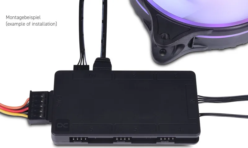
Proper installation guarantees longevity and system safety. Always disconnect the main power source by unplugging the cord from the wall socket before touching internal components. The motherboard output for ARGB must be a three-pin terminal, as four-pin connections risk damaging the controller. Secure mounting is straightforward using included Velcro strips. Peel the protective films from the adhesive tape and attach the controller firmly to the computer case. This method allows for easy detachment later if reconfiguration becomes necessary. Removing the upper protective film reveals the sticky surface for the base, while the second layer secures the device to the chassis.
Technical Performance Details
Connect the 2-pin aRGB and 4-pin PWM cables to your motherboard first. Ensure the ARGB output is strictly a 3-pin terminal, as improper connection can result in permanent damage. Connect the 2-pin aRGB IN and 4-pin PWM plug directly to the controller. Then attach the SATA power plug from your power supply to the SATA power input of the controller. Ensure power is OFF during this process. Connect the 4-pin fans to the relevant sockets. The M1 socket carries the tacho signal and must be populated first. Finally, connect the 3-pin aRGB connectors to the relevant sockets for lighting control. Remove the upper protective film of the adhesive tape and stick it under the controller. Now remove the second protective film and stick the controller to the computer case as shown. The controller can be detached again through the Velcro layer. This ensures that tools or fingers do not accidentally damage the unit during disassembly. Technical performance remains a priority for stable operation. The controller handles a maximum power consumption of 22.5 W drawn at 4.5 A. Organizing internal PC components leads to better airflow and aesthetics. This splitter provides reliability for those building high-performance rigs.
Conclusion for Builders
This tool is essential for clean builds requiring centralized control over multiple peripherals simultaneously. Users can find detailed installation guidance through official support channels in Germany. Ensure power safety during setup and verify all connection types to avoid electrical issues. The combination of fan control and light distribution offers flexibility that motherboards cannot always provide alone.
Search for 67,706 Manuals online


Type-in Brand or Model
Tom Schneider
7 months ago
Is the controller compatible with ARGB and PWM fans, and does it include all mounting accessories?
Manual.ly
7 months ago
Yes, the controller is fully compatible with both ARGB and PWM fans. All necessary accessories are included in the package, such as adhesive pads for installation. It is priced well and serves as a complete alternative for your setup.