
Manual.ly Logo

Weidmuller Multi-Stripax PV Manual

0.0 · 0 Ratings

PDF manual · 2 Pages

English

M: qwen/qwen3.5-flash-20260224
page

/ 2

Loading...
1335207b14db644855628ebc2866834557b4 page 1
DEUTSCH
1. Anschlag aufstecken
Nicht notwendig bei Werkzeug mit angeschraubten
Locator (siehe Abb. 5.1).
2. Anschlag einstellen
Nicht notwendig bei Werkzeug mit angeschraubten
Locator (siehe Abb. 5.1).
Leiter abisolieren.
3. Leiter abisolieren
Passende Abisolierstation wählen. Leiterentnahme
bei zusammengedrückten Griffen.
4. Leiter schneiden
Achtung:
max. Schneidleistung:
0,08 mm
2
-6,0 mm
2
feindrähtig
5.
Vorbereitung zum Wechsel der Abisoliereinheit
Werkzeug mit aufgesteckten Locator:
Anschlag abziehen.
Werkzeug mit angeschraubten Locator:
Siehe Abb. 5.1 und 5.2.
5.1 Schraube lösen und Anschlag abziehen.
5.2 Anschlag abziehen.
6. Wechsel der Abisoliereinheit
Schrauben lösen und entfernen.
Werkzeug leicht öffnen.
Abisoliereinheit komplett oben und unten heraus-
ziehen.
6.1 Die neue Abisoliereinheit in umgekehrter Rei-
henfolge einbauen.
7. Wechsel des Schneidmessers
a) Schrauben der Messerabdeckung lösen und
Abdeckung abnehmen.
b) Schraube des Schneidmessers lösen.
c) Das Anzugsdrehmoment für die Schraube des
Schneidmessers beträgt 0,4 Nm.
Neues Schneidmesser in umgekehrter Reihenfol-
ge einbauen.
Zusätzliche Hinweise
Bitte treffen Sie immer geeignete Schutzmaßnah-
men und beachten Sie die für Sie gültigen Unfall-
verhütungsvorschriften.
1. Anwendungsbereich
Das Werkzeug ist nur für die in der Betriebsan-
leitung beschriebene Anwendung bestimmt. Eine
andere Verwendung kann zu Unfällen oder Zerstö-
rung des Werkzeugs führen.
2. Wartung
Das Werkzeug muss in Abhängigkeit der Einsatz-
häugkeit und Beanspruchung regelmäßig auf
einwandfreie Funktion geprüft werden. Sollten ent-
sprechende Prüfungen vor Ort nicht möglich sein,
können diese vom Hersteller vorgenommen werden.
3. Reparaturen
Das Werkzeug darf nur durch eine Elektro-Mecha-
nikerfachkraft bzw. durch den Hersteller repariert
werden, andernfalls können Unfälle für den Betrei-
ber entstehen.
ENGLISH
1. Fit wire stop
Not necessary for tool with screwed-on locator
(refer to Figure 5.1).
2. Position wire stop
Not necessary for tool with screwed-on locator
(refer to Figure 5.1).
Strip wire of insulation
3. Strip insulation
Select appropriate insulation stripping groove. Re-
move the wire with the handles pressed together.
4. Cut wire
Caution:
max. wire dimensions:
exible: 0.08 mm
2
-6.0 mm
2
5.
Preparation for changing the stripping unit
For tool with attached locator:
Remove wire stop.
For tool with screwed-on locator:
Refer to Figures 5.1 and 5.2.
5.1 Loosen screw and remove the end stop.
5.2 Remove the end stop.
6. Replacing the stripping unit
Unscrew and remove screws.
Open tool slightly
Pull out the top and bottom of stripping unit com-
pletely.
6.1 Install the new stripping unit in the reverse
order.
7. Replacing the blade set
a) Loosen screws of the blade cover and remove
the cover.
b) Loosen screw of the cutting blade.
c) Use 0.4 Nm torque when tightening the screw
of the cutting blade.
Install the new blade in the reverse order.
Additional notes
Please always implement suitable safety meas-
ures and observe all applicable accident preven-
tion regulations.
1. Field of application
The tool is designed for use in applications de-
scribed in the operating instructions only. Using
this tool for tasks other than those described may
lead to accidents or the destruction of the tool.
2. Maintenance
Subject to the frequency of use and type of serv-
ice, the tool must be checked regularly to ensure
awless functioning. In the event that appropriate
tests are not possible on site, these can be con-
ducted by the manufacturer.
3. Repairs
The tool must only be repaired by an electro-
mechanical specialist or by the manufacturer,
otherwise operator accidents may result.
FRANÇAIS
1. Installer la butée
Pas nécessaire sur pince avec centreur vissé
(voir Fig. 5.1).
2. Régler la butée
Pas nécessaire sur pince avec centreur vissé
(voir Fig. 5.1).
Dénuder le conducteur.
3. Dénuder le conducteur
Sélectionner le poste de dénudage adéquat. Retrait
du conducteur lorsque les poignées sont serrées.
4. Couper le conducteur
Attention :
Capacité de coupe max. :
0,08 mm
2
-6,0 mm
2
en l souple
5.
Préparation au changement de l’unité de dénudage
Pince avec centreur monté :
Enlever la butée.
Pince avec centreur vissé :
Voir Fig. 5.1 et 5.2.
5.1 Desserrer la vis et retirer la butée.
5.2 Enlever la butée.
6. Changement de l’unité de dénudage
Desserrer et ôter les vis.
Ouvrir légèrement la pince.
Ôter entièrement l’unité de dénudage en haut et
en bas.
6.1 Monter la nouvelle unité de dénudage en
ordre inverse.
7. Remplacement du couteau de coupe
a) Desserrer les vis du capot des tranchants et
retirer le capot.
b) Desserrer la vis du couteau de coupe.
c) Le couple de serrage de la vis du couteau de
coupe est de 0,4 Nm.
Monter un nouveau couteau de coupe en ordre
inverse.
Autres remarques
Veuillez toujours prendre des mesures appropriées
et respecter les prescriptions de prévention des
accidents en vigueur pour vous.
1. Champ d‘application
La pince n‘est destinée qu‘à l’utilisation décrite
dans le mode d‘emploi. Un autre emploi peut en-
traîner des accidents et la destruction de l’outil.
2. Entretien
Il convient de contrôler régulièrement le fonction-
nement impeccable de la pince en fonction de la
fréquence d‘utilisation et de la sollicitation de celle-
ci. Si les contrôles s’y rapportant ne peuvent être
effectués sur place, ceux-ci peuvent être effectués
par le fabricant.
3. Réparations
La pince ne peut être réparée que par un électro-
mécanicien compétant ou par le fabricant. A
défaut, il pourrait en résulter des accidents pour
l‘utilisateur.
ITALIANO
1. Inserire l’arresto
Non necessario nel caso dell’utensile con Locator
avvitato (vedi Fig. 5.1).
2. Regolare l’arresto
Non necessario nel caso dell’utensile con Locator
avvitato (vedi Fig. 5.1).
Isolare il conduttore.
3. Isolare il conduttore
Selezionare la stazione di isolamento più ido-
nea. Rimozione dei conduttori con impugnature
schiacciate.
4. Tagliare il conduttore
Attenzione:
Potenza di taglio max.:
0,08 mm
2
-6,0 mm
2
con lo di precisione
5.
Preparazione alla sostituzione dell’unità di spel-
latura
Utensile con Locator montato:
Rimuovere l’arresto.
Utensile con Locator avvitato:
Vedere Fig. 5.1 e 5.2.
5.1 Allentare la vite e slare l’arresto.
5.2 Slare l’arresto.
6. Sostituzione dell’unità di spellatura
Allentare le viti e rimuovere.
Aprire leggermente l’utensile.
Slare l’unità di spellatura completamente in alto
e in basso.
6.1 Per il montaggio della nuova unità di spellatu-
ra, seguire la procedura inversa.
7. Sostituire la lama da taglio
a) Allentare le viti della copertura lama e rimuo-
vere la copertura.
b) Allentare la vite del coltello.
c) La coppia di serraggio della vite del coltello è
di 0,4 Nm.
Per il montaggio del coltello, seguire la procedura
inversa.
Altre avvertenze
Adottare sempre le misure di protezione appro-
priate e attenersi alle norme antinfortunistiche in
vigore.
1. Campo d’impiego
L’utensile è destinato solo all’impiego descritto
nelle istruzioni per l’uso. Un impiego diverso può
provocare incidenti o la distruzione dell’utensile.
2. Manutenzione
La perfetta efcienza dell’utensile va controllata
regolarmente in relazione alla frequenza d’uso e
alle sollecitazioni. Se questi controlli non possono
venire eseguiti sul posto, essi possono essere
eseguiti dal fabbricante.
3. Riparazioni
L’utensile deve venire riparato solo da un tecnico
elettromeccanico o dal fabbricante, altrimenti pos-
sono vericarsi incidenti per l’utilizzatore.
ESPAÑOL
1. Insertar el tope
No es necesario cuando se utiliza una herramienta
con localizador atornillado (véase g. 5.1).
2. Ajustar el tope
No es necesario cuando se utiliza una herramienta
con localizador atornillado (véase g. 5.1).
Desaislar el cable conductor.
3. Desaislar el cable conductor
Seleccionar la estación de desaislado. Extracción
de conductores con asas presionas entre sí.
4. Cortar el cable
Atención:
máx. potencia de corte:
0,08 mm
2
-6,0 mm
2
de hilo no
5.
Preparación para sustituir la unidad de aislamiento
Herramienta con localizador acoplado:
Quitar el tope.
Herramienta con localizador atornillado:
Véase g. 5.1 y 5.2
5.1 Soltar el tornillo y quitar el tope.
5.2 Quitar el tope.
6. Sustitución de la unidad aisladora
Aojar y retirar los tornillos.
Abrir la herramienta ligeramente.
Desmontar completamente, arriba y abajo, la
unidad aisladora.
6.1 Montar la unidad aisladora nueva siguiendo
los mismos pasos en orden inverso.
7. Sustitución de la cuchilla
a) Soltar la cubierta de la cuchilla y retirarla
b) Soltar el tornillo de la cuchilla de corte.
c) El par de apriete del tornillo de la cuchilla de
corte es de 0,4 Nm.
Montar una cuchilla de corte nueva en orden
inverso.
Otras instrucciones
Tome las medidas de protección adecuadas y siga
siempre las normas de prevención de accidentes
vigentes.
1. Ámbito de aplicación
La herramienta está destinada exclusivamente a
la aplicación descrita en las instrucciones de ser-
vicio. Cualquier otro tipo de uso puede conducir a
accidentes o a la inutilización de la herramienta.
2. Mantenimiento
El correcto funcionamiento de la herramienta de-
berá ser vericado regularmente en dependencia
de la frecuencia de su uso y de la solicitación a
que esté sometida. Si dicha vericación no fuese
posible sobre el terreno, podrá hacerse cargo el
fabricante de dichos trabajos.
3. Reparaciones
La herramienta sólo deberá ser reparada por un
electromecánico especializado o por el fabricante;
de otra forma pueden producirse accidentes para
el operador.
1 2
5.2
3 4
5 5.1 6
6.1 7

Chat with your Weidmuller Multi-Stripax PV manual using AI

Get instant AI answers from your Weidmuller Multi-Stripax PV manual

Ask anything about the Weidmuller Multi-Stripax PV. Answers come from this manual, with the pages they are based on.

Ask a Question

0/1000

Do you recommend Multi-Stripax PV?

Yes No

Frequently Asked Questions

A

This tool is designed for flexible wires with a cross-section ranging from 0.08 mm2 to 6.0 mm2. It is optimized for fine stranded cables often used in photovoltaic applications.

Is this answer helpful?

A

Remove the blade cover screws and take off the cover. Loosen the blade screw. Install the new blade in reverse order. Tighten the screw with a specific torque of 0.4 Nm to ensure safety and blade retention.

Is this answer helpful?

A

Repairs must be conducted only by an electro-mechanical specialist or the manufacturer. Unauthorized repairs can lead to operator accidents and safety hazards. Do not attempt to fix internal mechanisms yourself.

Is this answer helpful?

A

No, fitting a wire stop is not necessary for tools with a screwed-on locator. Refer to the specific figure in the manual for your model configuration. Follow the instructions for removing the end stop if needed.

Is this answer helpful?

A

Maintenance frequency depends on the intensity of usage and type of service. The tool must be checked regularly to ensure flawless functioning. If checks cannot be done on-site, contact the manufacturer for service.

Is this answer helpful?

A

Always implement suitable safety measures and observe valid accident prevention regulations. Wear personal protective equipment during operation to minimize risk of injury while working with electrical wires.

Is this answer helpful?

A

This tool is designed for flexible wires. Using it for other tasks may lead to accidents or destruction of the tool. Adhere to the application described in the operating guide to prevent damage.

Is this answer helpful?

M: qwen/qwen3.5-flash-20260224

Advantages and Disadvantages

Advantages

  • Adjustable wire stop for flexible positioning
  • Replaceable stripping unit for extended life
  • Precise torque control specified for blades
  • Durable construction for industrial environments
  • Handles flexible wire sizes from 0.08 to 6.0 mm2
VS

Disadvantages

  • Limited to flexible wire strands only
  • Requires specialist for major repairs
  • Specific torque needed for blade installation
  • Regular maintenance checks required for safety
  • Can be damaged by misuse or wrong application
M: qwen/qwen3.5-flash-20260224

Product Specification

Handle

Plastic

Wire Stripping Range

0.0039-0.0093 in^2

Total Length

9.84 in

Weight

1.21 lbs

M: qwen/qwen3.5-flash-20260224

Product Description

Revolutionizing Wire Stripping Efficiency

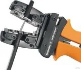
The Weidmueller Multi-Stripax PV Wire Stripper 250mm Manual stands as a critical tool for professionals dealing with photovoltaic installations and electrical wiring. This manual tool offers precision when stripping insulation from flexible conductors. It simplifies the process of preparing wires for connections, ensuring safety and reliable outcomes in your electrical projects. Whether in solar farm maintenance or residential wiring, this device delivers consistent results for high quality connections. It is engineered to meet the demands of modern infrastructure and rigorous safety standards.

Precision Cutting and Stripping

Designed for flexibility and accuracy, this device handles wire dimensions ranging from 0.08 mm2 to 6.0 mm2. The operator selects the appropriate insulation stripping groove to match the cable thickness perfectly. Removing the conductor is done with the handles pressed together, ensuring a clean cut without damaging the internal strands. Maximum cutting performance is optimized for fine stranded wires, making it ideal for delicate PV applications. The wire stop can be positioned easily unless a screwed-on locator is utilized which changes the setup process. Users must choose the right station for insulation stripping to ensure the best results during the work.

Maintenance and Component Replacement

Longevity depends on proper care and adherence to schedule. Users should regularly check for flawless function based on usage frequency and service type. Replacing parts requires specific steps to avoid damage. To change the stripping unit, unscrew the screws and pull the unit out completely from the top and bottom. For blade replacement, loosen the screws on the blade cover carefully. Tighten the cutting blade screw with a torque of 0.4 Nm for optimal safety and performance. This modularity allows field technicians to maintain peak performance without replacing the entire tool unnecessarily. The device supports both attached and screwed-on locators for versatile stopping positions during operation cycles. Ensure the workspace remains clean and debris-free to facilitate easier maintenance tasks. If repairs are needed beyond user replacement, contact the manufacturer or specialist.

Safety and Operational Guidelines

Always implement suitable safety measures during every operation. This tool is designed strictly for the applications described in the operating documentation. Misuse can lead to accidental damage or safety hazards for the operator. All operators must wear appropriate personal protective equipment to minimize risk. Maintenance must be conducted by qualified personnel if on-site tests are impossible to perform correctly. Only authorized electro-mechanical specialists should perform repairs to prevent operator accidents and equipment failure. Adhering to these protocols protects the operator and the longevity of the asset significantly. Failure to observe regulations may result in injuries.

Notes

  • Ensure handles are closed during wire removal to prevent slips.
  • Follow local accident prevention regulations always.
  • Use torque wrench for zero tolerance errors on blades.
  • Regular inspections are mandatory for safety compliance.
  • Consult manufacturer if field checks fail.
  • Check for wear on blades frequently.
  • Do not use for other than fine stranded wires
M: qwen/qwen3.5-flash-20260224

© Copyright 2026 Manual.ly