
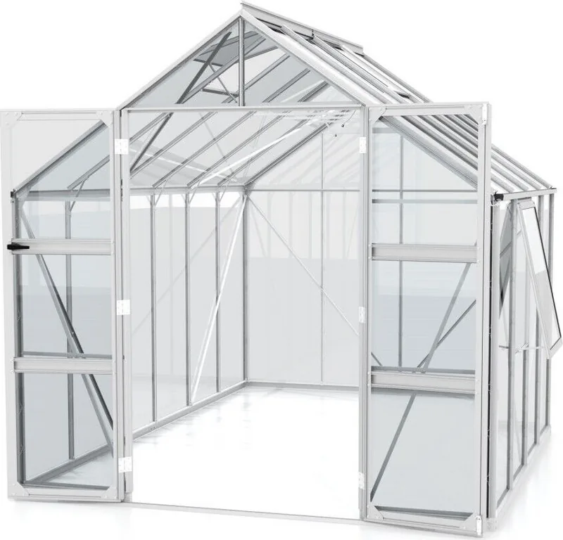
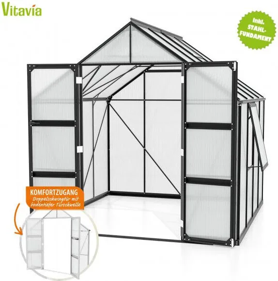
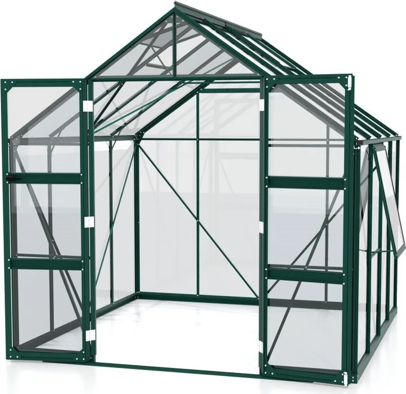
Vitavia Olymp 6700 Manual
0.0 · 0 Ratings
PDF manual · 84 Pages
English



Loading...

4
SICHERHEITSVORKEHRUNGEN
SITE SELECTION
Always try to select a sunny location, sheltered
from the wind as much as possible.
IMPORTANT
Before assembling your new greenhouse,
please check that all parts in the provided list
are included. Please take each bundle out of
the packaging in order to identify the parts
better.
It is important that the opened bundles do not
get mixed with one another.
If something is missing please contact your
retailer.
Nuts (1002) - Max. tightening torque 3Nm.
NECESSARY TOOLS
Screw drivers (Normal and Crosshead PH2),
10 mm socket spanner or wrench, 10 mm
combination spanner, knife, measuring stick,
spirit level, Accu-drill with adjustable torque.
MAINTENANCE
The greenhouse should be thoroughly washed
with a gentle detergent occasionally. Please
check that the detergent used does not react
aggressively with aluminium or the glass xing
clips.
Ensure that the upper and lower door tracks
are cleaned regularly to avoid a build-up of
debris.
0. BASE
Important! The base must be exactly square
and level. A zinc-coated steel base is available
as an accessory for all greenhouse models.
(Attention! Only when the greenhouse has to
be located in a very windy and unprotected
location: Drill through both the prole at the
base of the greenhouse and the steel base,
and connect them with nuts and bolts.)
If you would rather construct your own stone
or concrete foundation, please follow the
dimensions specied in diagram 0. Treated
wooden beams at least 18 mm high and not
more than 32 mm wide should be positioned
between the stone/concrete foundation and
the aluminium frame, and connected to the
foundation with 50 mm long bolts (not pro-
vided).
Foundations must extend down below the frost
level.
Diagrams in a single frame show the view
from inside the greenhouse. Those
enclosed in a double frame show the view
from outside the greenhouse.
1. SIDE ELEMENTS
Lay all of the parts on the oor and connect
them loosely.
At this stage it is necessary with each vertical
aluminium bar (2055) to include an extra
connecting bolt, to later connect corner braces
(2056) (1.5). On the outside bars (2055)
include one additional extra bolt, to also
connect cross braces (2033) (1.2).
Loosely connect the corner plate (1092) (1.1).
In step 4 the corner plate bolts must also be
connected to the gable ends.
2. PLAIN GABLE END
Lay all of the parts on the oor and connect
them loosely.
Include two extra connecting bolts in the
vertical bars (2041 and 2042) to connect the
cross braces (2.2) and (2.6). In the vertical bar
(2101) please include only one extra bolt.
3. DOOR GABLE END
Lay all of the parts on the oor and connect
them loosely.
The door runner bars (1347) will be connected
to the horizontal bar (2048). Connect each of
these loosely from the outside with three bolts
and two nuts.
Connect (5001) and (5002) as shown in (3.10)
(3.11) with a nut.
As in step 2, please include two extra bolts in
both vertical bars (2041) and (2042) (3.3).
4A. CONNECTING THE SEPARATE
ELEMENTS
Bolt the side elements to the end elements
(4.1) & (4.2).
Loosely connect the corner plate (1092) above
the eaves (4.3).
Assemble the ridge bar and then the corner
plates (1092) on the gable ends (4.4/4.5).
Connect the door runner supports (2043) to
the door runner bars (1347) using washer
(6060) (4.1) and to the gable end using bolt
(4201) and spacer (1310) (4.3) (4.6).
4B. CONNECTING THE SEPARATE
ELEMENTS
Connect the roof glazing bars (2055) between
the eaves (4.7) and the ridge bar (4.8). Insert
extra bolts into each glazing bar depending on
which house you have bought. The number is
indicated in a circle on each bar and to be
read beginning from both ends.
The corner braces (2056) (4.7), the roof
braces (2057) (4.9) and the cross braces
(2033) (4.11) (4.12) (4.13) can now be
connected.
Now position your greenhouse on the
prepared base/foundation and connect loosely.
Please do not over tighten. (max. 3Nm)
Adjust the greenhouse until it is completely
square and tighten all bolts.
Please do not over tighten.
Press the end protectors (1017) and (1018)
onto the prole ends (4.10).
5L and 5R. DOORS
Attention: Do not stand the assembled
001.01.2009
1. PLEASE READ THESE INSTRUCTIONS CAREFULLY AND COMPLETELY BEFORE ASSEMBLING YOUR GREENHOUSE.
2. Sharp edges and corners can cause injury. Always wear protective glasses, gloves, shoes and headgear when handling the aluminium proles, glass and
polycarbonate sheets. Broken glass is a safety hazard – always clear up immediately and dispose of with care.
3. The product you have purchased is intended only for growing plants and should only be used for this purpose. When used for other purposes we will take
no responsibility.
4. It is recommended that this greenhouse is assembled by two people.
5. Should you encounter difculties constructing this house, or in tting the glass or polycarbonate sheets, please contact your retailer
– do not use force!
6. The greenhouse must always be anchored.
Assembly Instructions
Safety Warning
EN
Quick check
I'm not a robot
Incorrect answer, please try again.
Chat with your Vitavia Olymp 6700 manual using AI
Get instant AI answers from your Vitavia Olymp 6700 manual
Ask anything about the Vitavia Olymp 6700. Answers come from this manual, with the pages they are based on.
Olymp 6700 Maintenance Schedule
Interval
Maintenance task
In the manual
Occasionally
Wash greenhouse
Thoroughly wash with gentle detergent occasionally. Ensure detergent does not react aggressively with aluminium or glass clips.
Show in the manual
(page 4)
Regularly
Clean door tracks
Clean upper and lower door tracks regularly to avoid debris build-up.
Show in the manual
(page 4)
Ask a Question
0/1000
Do you recommend Olymp 6700?
Yes NoProduct Specification
Frame
Aluminium
Area
72.08 sq ft
Special features
2 roof windows, side-hung windows, rain gutter, lockable
Door
Double swing door
Dimensions (LxWxH)
101.18x103.54x100in
Weight
186.93 lb
Scope of delivery
Steel foundation
Product Description
Search for 67,706 Manuals online


Type-in Brand or Model