
Vitavia Ida 5200 Manual
PDF manual · 28 Pages
English



Quick check
Incorrect answer, please try again.
Chat with your Vitavia Ida 5200 manual using AI
Get instant AI answers from your Vitavia Ida 5200 manual
Ask anything about the Vitavia Ida 5200. Answers come from this manual, with the pages they are based on.
Ida 5200 Maintenance Schedule
Thoroughly wash the greenhouse occasionally with a gentle detergent. Ensure the detergent does not react aggressively with aluminium or glass fixing clips.
Clean the upper and lower door tracks regularly to avoid a build up of debris.
Ask a Question
Do you recommend Ida 5200?
Yes NoFrequently Asked Questions
The foundation must be exactly square and level. You can use the optional galvanized steel base or build a concrete/stone foundation with treated timber battens (18 mm high), fixed with 50 mm bolts. Foundations should extend below the frost level and be anchored appropriately.
Is this answer helpful?
The UV-resistant side is indicated by protective plastic film and printing on the panel edge; this side must face outward. Remove the film only after the pane is positioned in the greenhouse to avoid misidentification and allow for thermal expansion.
Is this answer helpful?
Recommended tools: flat and PH2 screwdrivers, 10 mm spanner/socket, measuring stick, spirit level and an accu-drill with adjustable torque. Nuts (part 1002) should be tightened to a maximum of 3 Nm to avoid over-tightening.
Is this answer helpful?
Roof glazing uses wind-fixing strips and extra bolts in glazing bars for vents and reinforcements. Side glazing uses spring clips and glass-retaining clips or, for polycarbonate, screws and washers (included with panes) after drilling 2 mm pilot holes to secure panels and allow for expansion.
Is this answer helpful?
A double sliding door can be positioned in any two adjacent front fields except corner fields. Two single doors can be arranged on sides or front in various combinations. Plan door locations before side assembly as fields adjacent to door openings require middle braces.
Is this answer helpful?
Clean occasionally with a gentle detergent that won’t attack aluminum or glazing clips. Regularly clear upper and lower door tracks to prevent debris buildup, clear gutters and downpipes, and remove snow from the roof to avoid overload; check fasteners after about two weeks.
Is this answer helpful?
Wear protective glasses, gloves and sturdy footwear; handle glass and polycarbonate with care to avoid cuts. Assemble with two people, anchor the greenhouse, avoid using force when fitting glazing, and follow instructions for wind, snow and ventilation safety.
Is this answer helpful?
Advantages and Disadvantages
Advantages

- Space-saving lean-to design mounts against a wall to maximize sunlight and shelter.
- Durable aluminum frame with pre-drilled profiles for accurate, repeatable assembly.
- 4 mm multiwall polycarbonate glazing offers insulation, impact resistance and UV protection.
- Flexible door and vent options (single/double sliding doors, roof vent) for ventilation control.
- Comprehensive manual details parts, foundation, glazing and finishing for DIY assembly.
Disadvantages

- Requires accurate, square foundation and correct anchoring for long-term stability.
- Some parts and fixings (wall screws, drill, certain fasteners) are not supplied.
- Polycarbonate panels need careful handling and correct side orientation (UV film).
- Assembly can be complex and generally needs two people and a set of specific tools.
- Roof snow loads and high winds require proactive clearing/support and secure fixing.
Product Specification
Glazing
Polycarbonate 4mm (Twin-wall sheets)
Frame
Aluminum
Color
silver
Area
57.03 sq ft
Special features
Roof window, Rain gutter, lockable
Door
Double sliding door
Dimensions (LxWxH)
103.15x79.13x87.01in
Weight
98.90 lb
Product Description
Vitavia Ida 5200 HKP 4mm Lean-to Greenhouse alu Manual
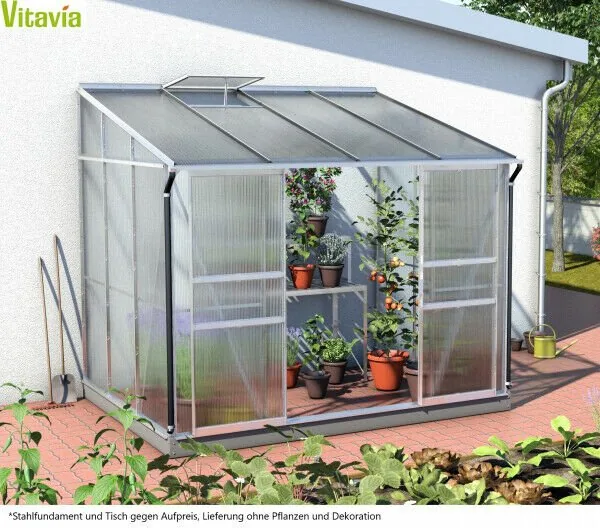
The Vitavia Ida 5200 HKP 4mm lean-to greenhouse is a sturdy, space-saving aluminum greenhouse designed to mount against a wall for optimal sun exposure and shelter. Built with precision extruded aluminum profiles and multiwall polycarbonate glazing (HKP), the Ida 5200 provides reliable insulation, light transmission and weather resistance. This manual-focused description highlights features, assembly guidance and practical advice for owners and DIY installers.
About the product
The Ida 5200 series combines a compact footprint with robust construction: corrosion-resistant aluminum framing, pre-drilled profiles for accurate alignment, and glazing engineered to allow thermal expansion while protecting plants. The 4 mm polycarbonate panels include a UV-protective side (clearly marked by film and printing) that must face outward; panels are slightly undersized to permit expansion. The greenhouse accommodates single or double sliding doors and optional roof vents, gutter/downpipe systems and a range of accessories for year-round use.
Assembly and installation highlights
The manual stresses a careful, methodical build: check part lists before starting, keep bundles separated, and use two people for safe handling. Foundations must be square and level; a galvanized steel base is available as an accessory or you can construct a concrete/stone base with treated timber battens to separate aluminum from masonry. Pre-drilled holes simplify wall mounting, but correct marking, drilling and fixing are essential for durability. Fasteners have a recommended maximum torque (nuts 3 Nm) and some polycarbonate panels are fastened with supplied screws and washers after drilling a small 2 mm pilot hole.
Glazing and finishing
Roof and side glazing differ slightly: roof glazing uses wind-fixing strips and additional bolts in glazing bars for vents and reinforcements; side glazing uses spring clips and glass-retaining clips or recommended screws and washers for extra security. The manual also covers correct placement of rubber seals, door runners, door gliders and rollers, plus installation of roof vents and window openers. Finish with neutral silicone if desired, install gutters and downpipes, and follow recommended maintenance: periodic washing with mild detergent and clearing door tracks and gutters.
Safety and maintenance notes
Always wear protective gear when handling aluminum, glass or polycarbonate. Anchor the greenhouse, close vents and doors in high winds, clear heavy snow from the roof, and check fasteners after two weeks. Keep the included model sticker on the door bar for part identification and retain the manual for future reference.
Notes:
- UV-protective film must face outwards; remove film only after installation.
- Use the appropriate door configuration (single or double) as planned before assembling.
- Max torque for certain nuts: 3 Nm.
Search for 67,706 Manuals online


Type-in Brand or Model