
Van der Valk Solar Systems ValkBox3 Manual
PDF manual · 21 Pages
English


Quick check
Incorrect answer, please try again.
Chat with your Van der Valk Solar Systems ValkBox3 manual using AI
Get instant AI answers from your Van der Valk Solar Systems ValkBox3 manual
Ask anything about the Van der Valk Solar Systems ValkBox3. Answers come from this manual, with the pages they are based on.
Ask a Question
Do you recommend ValkBox3?
Yes NoFrequently Asked Questions
The ValkBox 3 supports standard framed solar panels up to 2280 mm in length and up to 1150 mm in width, with panel frame mounting holes for M6 bolts. Clamp orientations are adjusted for three width ranges: 926–990 mm, 991–1070 mm and 1071–1150 mm.
Is this answer helpful?
Select the correct wind area from the wind map for your country, combine it with the building height in the ballast tables, then choose the required ballast in kg or number of tiles for G1 and G2. Divide ballast equally over rubber carriers and add minimum extra ballast of 2×1 tile (2×9 kg).
Is this answer helpful?
If the required ballast weight is higher than the space available under the system (marked as X in tables), the ValkBox 3 must be mechanically attached to the roof. Contact Van der Valk Solar Systems for recommendations and follow local structural rules.
Is this answer helpful?
The system is intended for flat roofs (bitumen, EPDM, concrete) and ground surfaces with a maximum pitch of 5°. For inclinations of 5° or more, mechanical fixing to the roof structure is mandatory.
Is this answer helpful?
Tighten hinge bolts B2 and B1 to a minimum torque of 9 Nm until there is no play. B1 bolts are temporarily removed during panel placement and must be retightened firmly after mounting.
Is this answer helpful?
Install the system in the roof’s middle zone; maintain an edge zone equal to 1/5 of the roof height (e.g., 1.2 m for a 6 m building height) to comply with wind load requirements per Eurocode EN1991‑1‑4.
Is this answer helpful?
Yes. A project‑specific structural design calculation must confirm the building can safely carry the additional loads from the PV system, wind and snow. Van der Valk disclaims liability if such checks are not performed.
Is this answer helpful?
Advantages and Disadvantages
Advantages

- Modular aluminium design for panels up to 2280×1150 mm, compatible with common flat‑roof coverings.
- Detailed ballast tables per country and wind area for safe, code‑based installations.
- Simple stepwise installation: clevis, curved supports, rubber carriers, ballast, secure hinge bolts.
- Cable management and recommended row pitch (2.20 m) included to minimize shading and tidy wiring.
- Clear rule to mechanically fix the system if ballast exceeds available space under the assembly.
Disadvantages

- Requires careful site‑specific design checks; installer remains responsible for structural verification.
- Ballast requirements can exceed space under the system, forcing mechanical attachment and extra work.
- Manual is not project specific and not legally binding—no direct liability from manufacturer.
- Maximum tile capacity is limited (17 tiles), which may be insufficient in high wind zones.
- System limited to flat roofs up to 5°; steeper roofs require mechanical fixing or different system.
Product Specification
Note
Prices partially include 0%-VAT tax rates for AT and DE
Type
Mount
Product Description
Van der Valk Solar Systems ValkBox 3 Installation Kit — Reliable flat‑roof PV mounting
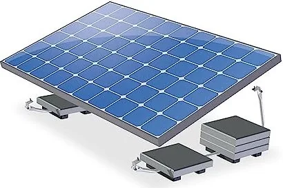
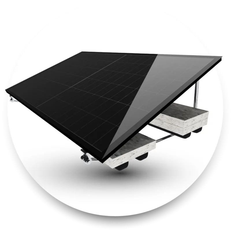
The Van der Valk Solar Systems ValkBox 3 Installation Kit (various versions) Manual describes a versatile, ballast‑based mounting system designed for standard framed PV panels on flat roofs (maximum pitch 5°). The ValkBox 3 supports panels up to 2280 mm long and 1150 mm wide and is compatible with common roof coverings such as bitumen, EPDM and concrete. Its modular aluminium components—clevis, curved supports, rubber ballast carriers and hinge bolts—allow installers to configure panel clamps for three panel width ranges and to arrange rows with optimal spacing to avoid shading.
This installation kit emphasizes wind and structural safety. Ballast tables are provided for many European countries and wind zones; installers must determine the site wind area and building height to select the correct ballast (tiles or kg) and follow rules for ballast distribution across rubber carriers. Where required ballast exceeds available space under the system, the manual instructs mechanical fixing to the roof. The manual also highlights the required “middle zone” placement on roofs (edge zone equals 1/5 of roof height) and mandates that a structural design check be used to confirm the building can accept additional loads from panels, wind and snow.
Installation is presented as a stepwise process: mount the clevis and curved supports, set clamps for the panel width, place rubber tile carriers, position ballast, attach panels and tighten hinge bolts (minimum torque 9 Nm). Cable routing and clamps are included; when installing multiple rows, a recommended pitch of 2.20 m (for a sun angle of 15°) helps prevent interrow shading. The manual also lists component counts, spare parts and general safety/disclaimer notes.
Overall, the ValkBox 3 kit is engineered for straightforward, repeatable rooftop installations with an emphasis on ballast design, safe positioning and clear mechanical instructions—suitable for installers who follow local building codes and perform project‑specific checks.
Notes
- Always verify wind area and building height before selecting ballast.
- If required ballast cannot fit, mechanically fix the system to the roof and consult Van der Valk.
- Observe the middle zone roof placement and local structural regulations.
- Tightening torque for hinge bolts B1/B2: at least 9 Nm.
Search for 67,706 Manuals online


Type-in Brand or Model