Manual.ly Logo

Telwin Inverpulse 320 AQUA Manual

0.0 · 0 Ratings

PDF manual · 172 Pages

English

M: gpt-5.6-terra
page

/ 172

Loading...
211b4de455b5bb69156722aec3bb1707ba9f page 5
- 5 -
CONTINUOUSWIREWELDINGMACHINESFORMIG-MAGANDFLUXTIG,MMA
ARCWELDINGDESIGNEDFORPROFESSIONALANDINDUSTRIALUSE.
Note:Inthefollowingtexttheterm“weldingmachine”willbeused.
1.GENERALSAFETYCONSIDERATIONSFORARCWELDING
The operator should be properly trained to use the welding machine safely
and should be informed about the risks related to arc welding procedures, the
associated protection measures and emergency procedures.
(Pleaserefertotheapplicablestandard“EN60974-9:Arcweldingequipment.
Part9:InstallationandUse).
- Avoiddirectcontactwiththeweldingcircuit:theno-loadvoltagesuppliedby
the welding machine can be dangerous under certain circumstances.
- When the welding cables are being connected or checks and repairs are
carried out the welding machine should be switched off and disconnected
from the power supply outlet.
- Switch off the welding machine and disconnect it from the power supply
outlet before replacing consumable torch parts.
- Make the electrical connections and installation according to the safety rules
and legislation in force.
- The welding machine should be connected only and exclusively to a power
source with the neutral lead connected to earth.
- Make sure that the power supply plug is correctly connected to the earth
protection outlet.
- Do not use the welding machine in damp or wet places and do not weld in the
rain.
- Do not use cables with worn insulation or loose connections.
- Iftheweldingmachinehasaliquidcoolingunitthellingoperationsshould
be carried out with the welding machine switched off and disconnected from
the power supply outlet.
- Donotweldoncontainersorpipingthatcontainsorhascontainedammable
liquid or gaseous products.
- Do not operate on materials cleaned with chlorinated solvents or near such
substances.
- Do not weld on containers under pressure.
- Removeallammablematerials(e.g.wood,paper,ragsetc.)fromtheworking
area.
- Provide adequate ventilation or facilities for the removal of welding fumes near
the arc; a systematic approach is needed in evaluating the exposure limits for
the welding fumes, which will depend on their composition, concentration
and the length of exposure itself.
- Keep the gas bottle (if used) away from heat sources, including direct sunlight.
- Use electric insulation that is suitable for the torch, the workpiece and any
metal parts that may be placed on the ground and nearby (accessible).
This can normally be done by wearing gloves, footwear, head protection and
clothing that are suitable for the purpose and by using insulating boards or
mats.
- Alwaysprotectyoureyeswiththerelativelters,whichmustcomplywithUNI
EN 169 or UNI EN 379, mounted on masks or use helmets that comply with UNI
EN 175.
Use the relative re-resistant clothing (compliant with UNI EN 11611) and
weldinggloves(compliantwithUNIEN12477)withoutexposingtheskintothe
ultraviolet and infrared rays produced by the arc; the protection must extend
to other people who are near the arc by way of screens or non-reective
sheets.
- Noise:Ifthedailypersonalnoiseexposure(LEPd)isequaltoorhigherthan85
dB(A) because of particularly intensive welding operations, suitable personal
protective means must be used (Tab. 1).
- The ow of the welding current generates electromagnetic elds (EMF)
around the welding circuit.
Electromagneticeldscaninterferewithcertainmedicalequipment(e.g.Pace-
makers, respiratory equipment, metallic prostheses etc.).
Adequate protective measures must be adopted for persons with these types of
medical apparatus. For example, they must be forbidden access to the area in
which welding machines are in operation.
This welding machine conforms to technical product standards for exclusive
use in an industrial environment for professional purposes. It does not assure
compliance with the basic limits relative to human exposure to electromagnetic
eldsinthedomesticenvironment.
The operator must adopt the following procedures in order to reduce exposure
toelectromagneticelds:
- Fasten the two welding cables as close together as possible.
- Keep head and trunk as far away as possible from the welding circuit.
- Never wind welding cables around the body.
- Avoid welding with the body within the welding circuit. Keep both cables on
the same side of the body.
- Connect the welding current return cable to the piece being welded, as close
aspossibletotheweldingjoint.
- Do not weld while close to, sitting on or leaning against the welding machine
(keep at least 50 cm away from it).
- Do not leaveobjects inferromagnetic material inproximity ofthe welding
circuit.
- Minimumdistanced:20cm(Fig.N).
- ClassAequipment:
This welding machine conforms to technical product standards for exclusive
use in an industrial environment and for professional purposes. It does not
assure compliance with electromagnetic compatibility in domestic dwellings
and in premises directly connected to a low-voltage power supply system
feeding buildings for domestic use.
EXTRA PRECAUTIONS
-WELDINGOPERATIONS:
- In environments with increased riskof electric shock
-Inconnedspaces
-Inthepresenceofammableorexplosivematerials
ENGLISH
INDEX
1.GENERALSAFETYCONSIDERATIONSFORARCWELDING ...........................................................5
2.INTRODUCTIONANDGENERALDESCRIPTION ................................................................................ 6
2.1 INTRODUCTION ................................................................................................................................... 6
2.2 METAL WELDABILITY .......................................................................................................................... 6
2.3 STANDARD ACCESSORIES ................................................................................................................ 6
2.4 OPTIONAL ACCESSORIES ..................................................................................................................6
3. TECHNICAL DATA..................................................................................................................................6
3.1 DATA PLATE (FIG. A) ............................................................................................................................ 6
3.2 OTHER TECHNICAL DATA ................................................................................................................... 6
4.DESCRIPTIONOFTHEWELDINGMACHINE ..................................................................................... 6
4.1 CONTROL DEVICES, ADJUSTMENT AND CONNECTION (FIG. B) ................................................... 6
4.1.1 Welding machine with integrated wire feed ........................................................................................ 6
4.2 WELDING MACHINE CONTROL PANEL (FIG. C) ...............................................................................6
4.3 RECALLING AND STORING PROGRAMS .......................................................................................... 8
4.3.1 RECALLING MANUFACTURER’S PRE-STORED PROGRAMS ..................................................... 8
4.3.1.1 MIG-MAG SYNERGIC programs .................................................................................................... 8
4.3.1.2 OPERATION IN MANUAL MODE (“PRG 0”) ...................................................................................8
4.3.2 STORING AND RECALLING CUSTOMISED MIG-MAG PROGRAMS ............................................. 8
4.3.2.1 Introduction ...................................................................................................................................... 8
4.3.2.2 Storage capacity for customised MIG-MAG programs .................................................................... 8
4.3.2.3 Storage procedure (SAVE) .............................................................................................................. 8
4.3.2.4 Procedure for recalling a customised program (RECALL) .............................................................. 8
5. INSTALLATION ....................................................................................................................................... 8
5.1 PREPARATION ..................................................................................................................................... 8
5.2 HOW TO LIFT THE WELDING MACHINE (FIG. E) ..............................................................................8
5.3 POSITION OF THE WELDING MACHINE ............................................................................................8
5.4 CONNECTION TO THE MAIN POWER SUPPLY ................................................................................. 8
5.4.1 Note ................................................................................................................................................. 8
5.4.2 Plug and outlet.................................................................................................................................... 8
5.5 CONNECTION OF THE WELDING CABLES ......................................................................................8
5.5.1 MIG-MAG WIRE WELDING (FIG.F) ................................................................................................... 8
5.5.1.1 Connecting the gas bottle ................................................................................................................ 8
5.5.1.2 Connecting the torch ....................................................................................................................... 8
5.5.1.3 Connecting the welding current return cable ................................................................................... 8
5.5.2 TIG WELDING (FIG. G) ......................................................................................................................8
5.5.2.1 Connection to the gas bottle ............................................................................................................ 8
5.5.2.2 Connecting the welding current return cable ................................................................................... 8
5.5.2.3 Connecting the torch ....................................................................................................................... 8
5.5.3 MMA WELDING WITH COATED ELECTRODE (FIG. H) ................................................................... 8
5.5.3.1 Connecting the electrode-holder clamp ........................................................................................... 8
5.5.3.2 Connecting the welding current return cable ................................................................................... 9
5.5.4 WARNINGS ........................................................................................................................................ 9
5.6 LOADING THE WIRE REEL (FIG. I) ..................................................................................................... 9
5.7 REPLACING THE LINER IN THE TORCH (FIG. N) ..............................................................................9
5.7.1 Coiled hose for steel wires ................................................................................................................. 9
5.7.2 Synthetic hose for aluminium wires .................................................................................................... 9
6.WELDING:DESCRIPTIONOFTHEPROCEDURE ............................................................................... 9
6.1 MIG-MAG WELDING ............................................................................................................................. 9
6.1.1 SHORT ARC TRANSFER MODE....................................................................................................... 9
6.1.1.1 ROOT MIG TRANSFER MODE ...................................................................................................... 9
6.1.2 SPRAY ARC TRANSFER MODE ....................................................................................................... 9
6.1.3 PULSE ARC TRANSFER MODE ....................................................................................................... 9
6.1.4 ADJUSTING THE WELDING PARAMETERS IN MIG-MAG .............................................................. 9
6.1.4.1 Protective gas ................................................................................................................................. 9
6.1.4.2 Welding current .............................................................................................................................10
6.1.4.3 Arc voltage and arc pinch-off ......................................................................................................... 10
6.1.5 BI-LEVEL AND PULSE ON PULSE OPERATION............................................................................ 10
6.2 TIG (DC) WELDING ............................................................................................................................10
6.2.1 LIFT strike .........................................................................................................................................10
6.3 MMA WELDING WITH COATED ELECTRODES ............................................................................... 10
6.4 WELD QUALITY ..................................................................................................................................10
7. MAINTENANCE ................................................................................................................................... 10
7.1 ROUTINE MAINTENANCE ................................................................................................................. 10
7.1.1 Torch ............................................................................................................................................... 10
7.1.2 Wire feeder ....................................................................................................................................... 10
7.2 EXTRAORDINARY MAINTENANCE .................................................................................................. 10
8.TROUBLESHOOTING(TAB.8) ............................................................................................................ 10
page page

Chat with your Telwin Inverpulse 320 AQUA manual using AI

Get instant AI answers from your Telwin Inverpulse 320 AQUA manual

Ask anything about the Telwin Inverpulse 320 AQUA. Answers come from this manual, with the pages they are based on.

Ask a Question

0/1000

Do you recommend Inverpulse 320 AQUA?

Yes No

Frequently Asked Questions

A

It supports MIG-MAG welding in short, spray, pulse, and pulse-on-pulse modes, plus TIG DC and MMA coated-electrode welding. This makes it suitable for a broad range of professional workshop and industrial tasks.

Is this answer helpful?

A

With the correct wire, electrode, gas, and settings, it can be used for carbon steels, low-alloy steels, stainless steels, aluminium and its alloys, copper, nickel, titanium, and related alloys. MIG brazing on galvanized sheet is also supported with suitable consumables.

Is this answer helpful?

A

Synergic programs coordinate multiple welding parameters for selected conditions. The operator can choose a program and adjust a main value such as thickness, current, or wire speed, while related settings are calculated together for faster setup.

Is this answer helpful?

A

Yes. Customized MIG-MAG programs can be saved and recalled for synergic Short/Spray Arc, Pulse Arc, Pulse-on-Pulse, and manual Short/Spray Arc operation. Custom programs are not available for TIG or MMA modes.

Is this answer helpful?

A

Yes. It includes an integrated motorized four-roller wire feeder with independently adjustable pulling pressure. This arrangement is intended to provide controlled wire delivery during MIG-MAG welding.

Is this answer helpful?

A

The supplied equipment lists a MIG torch and gas-related accessories. A compatible water-cooled cooling unit is listed as an optional accessory, along with water-cooled torch options for applications that require them.

Is this answer helpful?

A

Use trained operators, correct earthing, dry working conditions, ventilation or fume extraction, and approved personal protective equipment. Keep flammable materials away, protect nearby people from arc radiation, and disconnect power before maintenance or wire-feed servicing.

Is this answer helpful?

M: gpt-5.6-terra

Advantages and Disadvantages

Advantages

  • Multi-process capability covers MIG-MAG, pulsed MIG-MAG, TIG DC, and MMA electrode welding.
  • Fifty-four synergic MIG-MAG programs simplify setup for repeatable welding conditions.
  • Manual mode and save/recall functions support precise custom procedures.
  • Integrated four-roller wire feeder is designed for stable, adjustable wire delivery.
  • Optional water cooling, spool gun, remote controls, and specialty torches extend flexibility.
VS

Disadvantages

  • Designed for professional industrial use, not for domestic environments or untrained operators.
  • TIG operation is DC only, so it may not suit applications requiring AC TIG.
  • Safe operation requires careful ventilation, grounding, PPE, and electromagnetic-field precautions.
  • Some advanced accessories, including the cooling unit and trolley, are optional.
  • Manual MIG-MAG settings can be incompatible if parameters are selected incorrectly.
M: gpt-5.6-terra

Product Specification

Power

10.5 kW (400 V)

Open-circuit voltage

78 V

Adjustment range

10-300 A (MMA/WIG/MIG/MAG/FLUX)

Electrodes

0.06-0.24 in (MMA)

Protection rating

IP23

Dimensions

46.85 x 45.28 x 23.62 in (H x W x D)

Weight

211.64 lb

M: gpt-5.6-terra

Product Description

Telwin Inverpulse 320 AQUA MMA/TIG/MIG/MAG/FLUX Inverter Welding Machine - Read, Download & Print Free

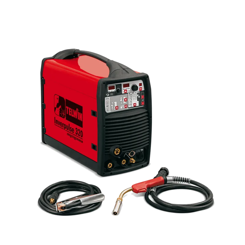
The Telwin Inverpulse 320 AQUA MMA/TIG/MIG/MAG/FLUX Inverter Welding Machine is a professional multi-process system built for demanding fabrication, repair, maintenance, and industrial welding work. Its inverter-based, three-phase power source combines MIG-MAG, pulsed MIG-MAG, TIG DC, and MMA electrode welding in one versatile platform. With an integrated wire feeder and microprocessor-controlled regulation, it is designed to help experienced welders adapt quickly to changing materials and job requirements.

Flexible Processes for Diverse Metals

For MIG and MAG work, the machine supports short arc, spray arc, pulse arc, and pulse-on-pulse operation. These options allow users to select a transfer mode suited to the material, thickness, and desired finish. The system is suitable for carbon steel, low-alloy steel, stainless steel, aluminium, and brazing applications when matched with appropriate wire and shielding gas. TIG DC capability expands its usefulness for steels, copper, nickel, titanium, and related alloys, while MMA mode supports coated electrodes for robust site and workshop repairs.

Synergic Control with Manual Freedom

A major strength of the Telwin Inverpulse 320 AQUA MMA/TIG/MIG/MAG/FLUX Inverter Welding Machine is its synergic programming. The unit provides 54 manufacturer-set MIG-MAG programs that coordinate parameters for specific welding conditions. Instead of adjusting every setting independently, the welder can choose a suitable program and refine the main working value, such as material thickness, current, or wire feed speed.

For specialists who prefer direct control, manual Short/Spray Arc operation permits independent adjustment of key values. The digital panel also supports customized MIG-MAG settings, allowing operators to save and recall optimized procedures. This is useful for repeat jobs, production work, and teams seeking consistent settings between shifts.

Wire Feed, Cooling, and Accessories

The integrated wire feeder uses a motorized four-roller puller with independently adjustable pressure, helping promote steady wire delivery. Standard equipment includes an argon bottle adapter, earth cable and clamp, pressure-reducing valve with two gauges, and a 3 m MIG torch. Optional equipment includes trolleys, remote controls, spool guns, aluminium kits, TIG torches, push-pull torches, and a water-cooled cooling unit for compatible high-duty applications.

Safety and Professional Use

This machine is intended for professional and industrial environments. Welding requires trained operation, suitable grounding, ventilation, and protection from fumes, fire, electric shock, ultraviolet radiation, burns, and moving wire-feed components. Use an approved welding helmet, gloves, flame-resistant clothing, footwear, and hearing protection where noise exposure requires it. Keep unauthorized people away and follow precautions around electromagnetic fields, particularly for people with medical devices or metal prostheses.

Note: Select consumables, wire, gas, polarity, and welding parameters according to the base material and process. Disconnect power before servicing the torch, wire feeder, cooling circuit, or electrical connections.

M: gpt-5.6-terra

© Copyright 2026 Manual.ly