

Supermicro Ice Lake-D Series Manual
PDF manual · 119 Pages
English



Quick check
Incorrect answer, please try again.
Chat with your Supermicro Ice Lake-D Series manual using AI
Get instant AI answers from your Supermicro Ice Lake-D Series manual
Ask anything about the Supermicro Ice Lake-D Series. Answers come from this manual, with the pages they are based on.
Ask a Question
Do you recommend Ice Lake-D Series?
Yes NoFrequently Asked Questions
It supports up to 256GB of ECC and Non-ECC RDIMM or UDIMM DDR4 memory with speeds up to 2933 MT/s across four slots.
Is this answer helpful?
BIOS updates are available on the Supermicro website. Download the file onto a bootable USB device and use the FLASH.BAT file to update.
Is this answer helpful?
Power down the system, remove the battery, short the CMOS clear pads for four seconds, then replace the battery and power on.
Is this answer helpful?
Yes, it features a Trusted Platform Module 2.0 header for hardware-based security functions and encryption.
Is this answer helpful?
Contact the distributor first for technical support. For hardware repairs, obtain an RMA number and ship the product prepaid.
Is this answer helpful?
The system requires a 24-pin ATX connector and an 8-pin 12V DC input for the CPU to ensure stable operation.
Is this answer helpful?
Advantages and Disadvantages
Advantages

- Supports up to 10 cores from the Intel Xeon D-1700 series
- Scalable memory up to 256GB DDR4 ECC and Non-ECC
- Multiple high-speed network ports including 25GbE SFP28
- Comprehensive health monitoring and management via BMC
- Compact Flex ATX form factor suitable for edge computing
Disadvantages

- Requires careful handling of static sensitive components
- Specific power supply requirements for stability
- Complex installation procedures for novice users
- Limited expansion compared to full-size ATX boards
- Reliance on professional technician installation and service
Product Specification
Chipset
System-on-Chip (SoC)
Fan Header
6 x Fan 4-Pin
LED Header
N/A
Buttons/Switches
N/A
Audio
N/A
Graphics
ASPEED AST2600 - Onboard
Wireless
N/A
RAID Level
0/1/5/10
Multi-GPU
N/A
Power Connectors
1 x 24-Pin ATX, 1 x 8-Pin EPS12V, 1 x Proprietary (12V)
Lighting
N/A
BIOS
1 x 32MB (256Mb)
USB Port Labeling
Link
Product Description
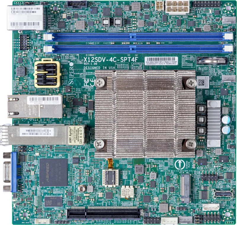
Supermicro X12SDV Series Overview
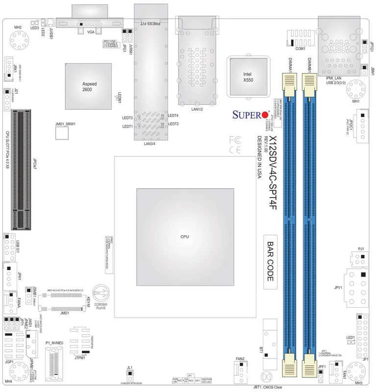
The Supermicro X12SDV series motherboards specifically the X12SDV-4C-SP6F and X12SDV-10C-SP6F models deliver exceptional compute density. These platforms are built upon the Intel Xeon D-1700 processor architecture offering configurations ranging from 4 to 10 cores. The thermal design power varies by model reaching up to 80W for top-tier options. This ensures that energy efficiency remains high even when the system is under heavy load. Memory capacity is scalable supporting up to 256GB of DDR4 modules. Users can choose between ECC and Non-ECC types providing flexibility for different security and performance requirements. Network flexibility is a primary selling point for data centers. Models like the X12SDV-8CE-SP4F include 25GbE SFP+ and SFP28 ports alongside standard Gigabit Ethernet connections. This allows administrators to upgrade bandwidth without swapping out the entire chassis. Storage options are equally versatile with three M.2 slots supporting PCIe 3.0 devices. Two PCIe 4.0 slots provide room for graphics accelerators or additional I/O cards. The onboard management features reduce the need for external monitoring hardware.
Supermicro has integrated comprehensive health monitoring into the BIOS. Voltage monitors track power stability for critical rails. Fan status monitors alert users if cooling solutions fail prematurely. The chassis intrusion header allows the system to detect unauthorized physical access to the hardware. Additionally the TPM 2.0 header supports encryption keys for secure boot processes. The system supports ACPI features for power management and allows recovery from AC power loss settings in the BIOS setup. Installation requires careful handling of electrostatic discharge precautions. A grounded wrist strap helps protect sensitive components during assembly. If issues arise troubleshooting procedures are available for power and video failures. Users should check memory compatibility lists regularly to avoid boot failure. For warranty claims contacting the vendor first is recommended before seeking return merchandise authorization. The text provided in the Supermicro Ice Lake-D Manual serves as a definitive guide for these protocols. With support for latest software standards maintaining these systems is straightforward. Regular BIOS updates ensure security patches are applied proactively. The UEFI BIOS Setup utility allows granular control over hardware settings. From boot order to power configuration every aspect can be customized. This level of control is why IT professionals prefer this platform for mission-critical applications. Always verify the specific version numbers when ordering replacement parts. Compatibility lists should be checked before purchase to ensure the system remains stable under peak loads. Referencing technical specifications helps prevent installation errors during initial setup. Users should also be aware that battery removal requires specific steps to prevent data loss. Removing power must be done carefully to maintain the integrity of the CMOS settings. Technical support procedures include checking beep codes if the system fails to boot. Referencing the Supermicro Ice Lake-D Manual further details the jumper settings for LAN and USB ports. This ensures that network interfaces are enabled or disabled as per the configuration needs of the facility. Security settings including Trusted Platform Module headers provide hardware-level encryption capabilities. These features make the board suitable for enterprise-grade deployments requiring high availability. The power supply requirements specify a 24-pin ATX connector with 8-pin input for CPU stability. Adhering to these electrical standards is crucial for preventing hardware damage.
Search for 67,706 Manuals online


Type-in Brand or Model