
Siedle Vario BTLM 650-04 Manual
PDF manual · 24 Pages
English



Quick check
Incorrect answer, please try again.
Chat with your Siedle Vario BTLM 650-04 manual using AI
Get instant AI answers from your Siedle Vario BTLM 650-04 manual
Ask anything about the Siedle Vario BTLM 650-04. Answers come from this manual, with the pages they are based on.
Ask a Question
Do you recommend Vario BTLM 650-04?
Yes NoVideo Manual
Siedle In-Home-Bus: Manuelle Programmierung
Frequently Asked Questions
Mount the unit so the camera center is approximately 1.60 m high. For systems without video, position the flush-mount housing center between 1.40 m and 1.60 m to ensure optimal user access and visibility.
Is this answer helpful?
Strip connection cables to a maximum of 3 cm near the wall, insert through the housing back, press them onto the housing base, secure with the provided cable clamps and wire-retaining brackets, then connect to the combination terminal strip following the wiring diagram.
Is this answer helpful?
Insert modules into the MR 611 slots opposite the movable locking bolt with light pressure and clip them in. To remove, insert the supplied Vario key in the opening between modules with light pressure; unlocking releases one or two modules. For extra security, use the anti-theft accessory (ZDS 601) and controller (DSC 602).
Is this answer helpful?
Use the sealing-film orientation rules (upper and right edges), overlap multi-row frames like roof tiles, fit the water deflector on surface mounts, close unused cable entries, and ensure combination frame sealing profile is open downward to prevent water ingress.
Is this answer helpful?
Release the module’s rear wire bracket and hook it into the retainer on the combination terminal strip; this secures the module for functional testing and measurements. Return the bracket to the rear after service.
Is this answer helpful?
For frames from 600×500 mm upward, use the recessed adjusting screw in the cross-shaped intermediate webs to level and support the combi-frame so that inserted modules present a flat front surface.
Is this answer helpful?
Clean regularly with mild soap and water solution, then dry with a soft cloth. Avoid pressing catch lugs backward to prevent material fatigue and check cable clamps and seals during maintenance.
Is this answer helpful?
Advantages and Disadvantages
Advantages

- Modular design for flexible multi-row installations and easy expansion.
- Secure, tool-assisted module locking and Vario key removal for controlled access.
- Combi terminal strip and standardized wiring ensure consistent, clear electrical connections.
- Sealing film and water deflector accessories support reliable weather protection.
- Service-friendly features: rear wire bracket for live testing and replaceable inscription inserts.
Disadvantages

- Precise sealing-film orientation and stacking rules increase installation complexity.
- Large combination frames may require corner removal or special-order frames.
- Multiple small parts (washers, clamps, clips) raise risk of misplacement during install.
- Material fatigue risk if catch lugs are accidentally engaged backwards.
- Installation demands careful alignment and occasional adjustment screw use for flush fronts.
Product Specification
Display
N/A
Detection Range
N/A
Protection Class
IP54
Scope of delivery
1x Outdoor unit
Dimensions
3.90x3.90x1.38in
Product Description
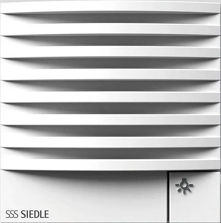
Siedle BTLM 650-04 Vario Bus Door Speaker Module Manual
The Siedle BTLM 650-04 Vario Bus Door Speaker Module is a modular door communication component designed for flexible residential and commercial entry systems. Built for the Siedle Vario platform, this module integrates with combination frames and mounting housings (surface, flush, hollow-wall) and works with ribbon-cable connection to the system’s combi terminal strip. It supports multi-row configurations and tool-assisted insertion and removal via the Vario key for secure, serviceable operation.
Installation emphasizes correct orientation and sealing: mounting height recommendations place camera center at approximately 1.60 m (1.40–1.60 m when no video). For uneven façades, included distance washers and a water deflector help ensure a watertight installation. The product uses a mounting frame and combination frame system with sealing film placement rules (upper and right edges, overlapping like roof tiles when stacked) to maintain waterproofing and neat front alignment of modules.
Wiring and connection follow a standardized procedure: strip cables to a maximum of 3 cm, press into the housing base, secure with cable clamps and wire-retaining brackets, and attach to the combination terminal strip which is seated by rotating it 45° then latching a quarter-turn. Large combination frames include an adjusting screw in the central cross to level intermediate webs and guarantee a flush front surface for inserted modules.
Modules clip into MR 611 module slots opposite the movable locking bolt and secure with light pressure; removal is via the supplied Vario key that releases one or two modules. For service, a wire bracket on the module’s rear can be engaged to test modules without full removal. Label inserts for call and information modules are removable and replaceable; Siedle provides optional water-repellent paper inserts and a lettering service for optimal identification.
The design pays attention to longevity and maintenance: catch lugs should not be engaged backwards to avoid material fatigue, unused cable entries must be closed, and surfaces should be cleaned with mild soap and dried with a soft cloth to preserve appearance.
Notes:
- Follow sealing film orientation and multi-row stacking rules to prevent water ingress.
- Use the adjusting screw in large combi-frames to align module fronts.
- Engage the wire-retaining bracket during service for safe live testing.
Search for 67,706 Manuals online


Type-in Brand or Model