
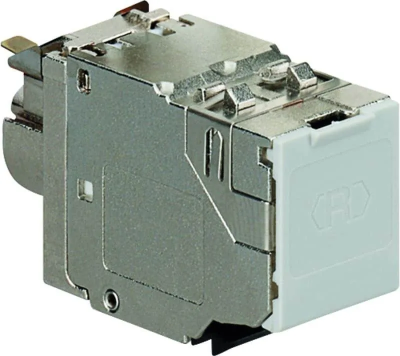
Rutenbeck UM-Cat.8.1/Class I 10G Manual
PDF manual · 2 Pages
English



Quick check
Incorrect answer, please try again.
Chat with your Rutenbeck UM-Cat.8.1/Class I 10G manual using AI
Get instant AI answers from your Rutenbeck UM-Cat.8.1/Class I 10G manual
Ask anything about the Rutenbeck UM-Cat.8.1/Class I 10G. Answers come from this manual, with the pages they are based on.
Ask a Question
Do you recommend UM-Cat.8.1/Class I 10G?
Yes NoFrequently Asked Questions
The Rutenbeck UM-Cat.8.1/Class I module supports data rates up to 40 Gbps over channel lengths up to 30 meters, making it suitable for high-speed backbone connections and data center interconnects.
Is this answer helpful?
Yes, it is designed specifically for insertion into standard keystone module cutouts, allowing for easy integration into wall plates and patch panels used in commercial and industrial settings.
Is this answer helpful?
Absolutely. The module is certified for PoE+ suitability according to IEEE 802.2at, capable of handling 500 mA operating current at 50 degrees Celsius ambient temperature.
Is this answer helpful?
You will need a cutting tool for trimming wires, parallel action pliers for securing the cover and tension relief, and standard crimping tools if preparing your own patch cables according to ISO standards.
Is this answer helpful?
While physically possible, using unshielded cables defeats the purpose of the shielded design and may result in signal degradation due to increased susceptibility to crosstalk and interference.
Is this answer helpful?
The module is rated for a minimum of 750 mating cycles, ensuring long-term durability for frequently plugged and unplugged connections in active network environments.
Is this answer helpful?
Advantages and Disadvantages
Advantages

- Supports Cat.8.1 Class I standards for 10G and 40G speeds
- Superior shielding protects against electromagnetic interference
- Compatible with both TIA/EIA-568-A and B wiring schemes
- Halogen-free material enhances fire safety and environmental compliance
- Robust tension relief system prevents cable strain and disconnection
Disadvantages

- Requires specific parallel action pliers for proper installation
- Strict adherence to cable preparation steps is necessary for function
- Higher cost compared to unshielded Cat.6A alternatives
- Limited ambient temperature range compared to some industrial grades
- Complex dismantling procedure requires reverse order of assembly
Product Specification
Type
Keystone Module (1x RJ-45, Cat8.1 Class I, via RJ-45 jack)
Features
fully shielded
Product Description
Rutenbeck UM-Cat.8.1/Class I 10G Universal Module: The Shielded Solution for High-Speed Networks
The Rutenbeck UM-Cat.8.1/Class I 10G Universal Module represents a significant advancement in structured cabling infrastructure, designed specifically for environments demanding maximum data integrity and speed. This shielded module is engineered to support Cat.8.1 standards, ensuring reliable performance up to 40 Gbps over short distances while maintaining backward compatibility with lower categories. Its robust construction makes it an ideal choice for modern data centers and high-performance enterprise networks where signal interference must be strictly controlled.
Designed for seamless integration into keystone module cutouts, this universal component offers exceptional flexibility during installation. The unit features a comprehensive tension relief system that secures the cable against mechanical stress, a critical factor in maintaining consistent transmission characteristics over time. The shielding provides superior protection against alien crosstalk and external electromagnetic interference, which are common challenges in dense cabling trays. By adhering to ISO/IEC 61935-2 standards for patch cables and connectors, the module ensures that the entire link meets rigorous certification requirements without compromise.
Installation is straightforward when following the precise guidelines provided by the manufacturer. The process involves careful preparation of the cable sheathing, proper handling of the braided shield, and meticulous arrangement of the four wire pairs within the internal distributor. The module utilizes a color-coded wire fixation system that simplifies termination for both TIA/EIA-568-A and TIA/EIA-568-B wiring schemes. Once the wires are correctly seated and trimmed flush, the cover is secured using parallel action pliers, locking the assembly firmly in place. A unique feature includes the potential for equipotential bonding, enhancing safety and grounding integrity in complex electrical environments.
Beyond its physical durability, the module boasts impressive technical specifications suitable for PoE+ applications. It supports a rated voltage of 72 V DC and can handle operating currents up to 500 mA at elevated temperatures. With a dielectric strength of 1,000 V between contacts and a minimum insulation resistance of 500 MΩ, the device ensures long-term reliability even under demanding electrical loads. The halogen-free construction further underscores a commitment to environmental safety and fire resistance. Whether deploying for new installations or upgrading existing infrastructure, the Rutenbeck UM-Cat.8.1 stands as a premium solution for professional network architects seeking uncompromising performance and ease of use.
Important Installation Notes
Ensure all patch cables used are tested according to ISO/IEC 61935-2 to prevent malfunctioning. Always verify that the dust protection cap is open before inserting the wire distributor. Use only parallel action pliers for securing the module cover and tension relief components to avoid damaging the housing.
Search for 67,706 Manuals online


Type-in Brand or Model