
Rutenbeck UM-Cat.6A iso 10G Manual
PDF manual · 2 Pages
English



Quick check
Incorrect answer, please try again.
Chat with your Rutenbeck UM-Cat.6A iso 10G manual using AI
Get instant AI answers from your Rutenbeck UM-Cat.6A iso 10G manual
Ask anything about the Rutenbeck UM-Cat.6A iso 10G. Answers come from this manual, with the pages they are based on.
Ask a Question
Do you recommend UM-Cat.6A iso 10G?
Yes NoFrequently Asked Questions
The Rutenbeck UM-Cat.6A iso module supports transmission bandwidths up to 500 MHz, meeting current standards for high-frequency connecting systems.
Is this answer helpful?
Yes, but you must use an appropriate adapter, such as the ADAP Kombi 154 006 05, to ensure proper connection and functionality.
Is this answer helpful?
Using non-norm-compliant cables or connectors may void warranty claims. You should only use components that correspond to valid EN/IEC standards.
Is this answer helpful?
Insert the longer wires perpendicular through the distributor, swivel the cable towards the spine, and push the distributor to the stop before securing it.
Is this answer helpful?
The documentation focuses on indoor cabinet usage. Ensure proper environmental protection if used in areas exposed to harsh conditions not covered by standard ratings.
Is this answer helpful?
Do not throw it in household waste. Bring it to a competent collection site for electrical and electronic devices as per EU and German laws.
Is this answer helpful?
Advantages and Disadvantages
Advantages

- Supports transmission bandwidths up to 500 MHz for high-performance networking
- Fully shielded design protects against electromagnetic interference
- Meets strict EN/IEC international standards for Category 6 systems
- Includes robust strain relief and mounting wedge for secure installation
- Compatible with standard RJ45 connectors and certified patch cables
Disadvantages

- Requires precise stripping and wire arrangement during installation
- Non-standard connectors require additional adapters for compatibility
- Warranty void if non-compliant cables or improper usage occurs
- Must be disposed of via specialized e-waste recycling programs
- Complex disassembly process requires specific tools like screwdrivers
Product Specification
Type
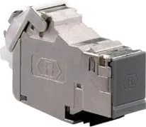
Keystone Module (1x RJ-45, Cat6a, via RJ-45 Jack)
Features
fully shielded
Product Description
Elevate Your Network with the Rutenbeck UM-Cat.6A iso Module
In the modern era of high-speed connectivity, ensuring your infrastructure can handle bandwidth demands up to 500 MHz is critical. The Rutenbeck UM-Cat.6A iso module stands as a premier solution for universal modular cutouts designed specifically for keystone jacks. This shielded component represents a sophisticated blend of electrical and mechanical engineering, tailored to meet rigorous international standards for Category 6 applications.
Designed for professionals who demand reliability, this universal module facilitates seamless integration into structured cabling systems. Its construction ensures that every connection maintains signal integrity while resisting electromagnetic interference. The product is engineered to support the latest transmission techniques, making it an ideal choice for data centers, office environments, and industrial settings where stability is paramount.
Installation is straightforward when following the provided guidelines, which emphasize precision in cable preparation. Users must strip the cable jacket carefully, manage the braided screen correctly, and arrange wire pairs according to the specific color codes. The module features a unique wire distributor and a mounting wedge system that secures the internal wiring against mechanical stress. A strain relief bar further protects the connection by clamping down on the cable jacket and screening, preventing damage during insertion or removal of patch cables.
The design prioritizes longevity and performance. By avoiding unnecessary pressure on the ports and ensuring proper cable routing within cabinets, the module prevents common failure points associated with poor installation practices. It adheres strictly to EN/IEC standards, guaranteeing compatibility with certified patch cables and connectors. This adherence to protocol ensures that the network operates at peak efficiency without compromising on safety or regulatory compliance.
Important Installation Notes
Proper handling is essential to maintain warranty coverage and optimal function. Always use adapters for non-RJ45 connector types and verify that all external components meet valid norms. Avoid tilting or pulling on cables during operation to prevent mechanical stress on the outlets.
Disposal and Compliance
This device complies with EU directives regarding low voltage and hazardous substances. End-users must dispose of the unit through designated electronic waste collection points rather than regular household trash, ensuring environmental safety and regulatory adherence.
Search for 67,706 Manuals online


Type-in Brand or Model