TEC
3
polarit
Operating temperature: 0°
Storage temperature: -1
Batter 6LR6
Miniature fuse: F1
F250mA,
DESCRIPTION OF
Symbol Description
V
Direct voltage (DC)
V
Alternating voltage (AC)
A
Direct current (DC)
A
Alternating current (AC)
Resistance (Ohm)
Acoustic continuit
Diode test
Signal generator
ºC
T
Fuse
Earth
Shockproof (safety class 2)
Caution, risk of danger
Danger of electric shock
SAFETY
This
voltage categor
The pr condition of the device and the
necessary
in these
correct measurements.
The
unit with regard to safet Defectiv test tips
must alway be replaced with new ones of
the t
• Never
cables are damaged or a malfunctions is
suspected.
•
use by measur
• Always disconnect the voltage-carr t
cable before
• Do not touch the metal tips of the test tips
during measurements.
• V measurements to ground may
only be conducted up to a maximum of
250 volts.
• Particular caution should be e
voltage measurements of:
>
>
CARE
• Before opening the device, the connection
plugs of the test tips must be disconnected
from the
to be
• defective miniature fuse may only be
replaced with
• After the housing opened, tester may
not
screw
• Always switch of
• Use only
ning
or solvent-based
DESCRIPTION OF OPERATING SECTION
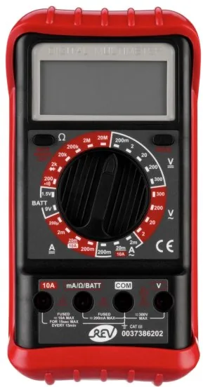
➀ Rotar
➁ Display
➂ COM
➃ V
➄ 10A socket
CONDUCTING
Caution!
The tester switches of automatically af
1
Measuring alternating
• Connect ➃
black tes ➂ socket.
• Set rotary switch to required alternating
voltage position
• Connect test cables to circuit; measured
values are shown in
Measuring direct
• Connect ➃
black tes ➂ socket.
• rotary switch to required direct voltage
position
).
is unknown then set the rotary
switch
ce
display is
• Connect the test cable to circuit measured
values and polarit of red test cable are
shown in
is positive „+").
Measuring direct
• Connect r➃ sock
test cable ➂
• Set rotary switch to requir dir curr
position (A
).
•
made and
• Measured values and polari-
ty of red test cable are shown in L
display (polarit of red test tip is
positive „+").
Measurement
For 1
• the “red” test cable to t 1
➄ socket and the “black” test cable to the
COM ➂
Measuring time: 10 sec., ne measurement
after
Measuring resis
Caution! Always
ments in
• If
a
all capacitors
• Connect ➃
black ➂
of red
• Set switc required value -
tion ().
• test tips to resistance to be tested;
measured values are shown
Diode tes
• Connect ➃
black ➂
of red
• Set rotar
" position.
•
tip to
•
In
will appear
GB
Testing continuity
• to ➃ black
test cable ➂ socket.
• Set rotar
" position.
• Connect test tips at beginning and end of
test
buzzing tone
Test signal ( Item N
• test is mea-
sure amplifier stages. It is not a continuit
tester!
• ➃
test cable ➂ socket.
• the rotar control switch to position
„
“
•
is in
• coupling capacitor must be connected
upstream
an electric
Measuring tem
(Item N
Insert special measuring cable with heat sen-
sor in socket N ➂ and ➃ . Connect sensor
to object to be measured. Measured value
appears in
REPLACING
MINIA
Caution:
opening housing.
The batter
appears
two screws on the
com pletely
Replace drained batter with a new one
of the same t (6LR6 9V-Block D). Pay
attention to
Item No. Item No.
DCV
• •
ACV
• •
DCA
• •
• •
• •
•
•
Temp.
•
•
Miniature fuse
The only be
very seldom, and when it does, it is almost
always due to
In this case you open the housing (as when
replacing battery) and replace the defec-
tive fuse wit
Observe
care instructions
MEASURING TOLERANCES
(AMBIENT TEMPERATURE 23°)
Measuring
range
Resolution
Measuring
accuracy
Alternating voltage
200 1
± 1
250 1V
Direct voltage
200 1
2V 1mV
± 0,8%
20V 1
200 1
250 1V ± 1
Direct curr
20A 0,0 ± 1
200A 0,
20 1A ± 1
20 1
200mA 1 ±
1 1 ± 2,0% +
Resistance Ω
200 0, ± 1
2000 1
20 1 ± 0,8%
200 1
2000K 1K ±
Temperature (Item
0037)
0°C ± 2.0%
CARACTERISTICAS TE
Display
ción automática
T
T
almacenamiento:
Pila: 6LR6
Fusible para
corrientes F1
F250mA,
ESPECIFICACIÓN DE
Simbolo Significado
V
T (DC)
V
T (AC)
A
Corriente alterna (DC)
A
Corriente alterna (AC)
Resistencia (Ohm)
Control de continuidad
Prueba diódica
Generador de signales
ºC
T
Fusible
T
Aislamiento protector (Clase 2)
Atención, Riesgo de peligro
Peligr
INSTRUCCIONES DE
Este cumple
con todos los requisitos de la directiva
en
dentro de la
El
to estricto de las instrucciones de seguridad
incluidas en este manual de manejo son
requisitos indispensables para una medición
correcta.
Las sondas de com probación y el controlador
digital multifuncional constituyen una unidad
en
osas deben cambiarse por otras nuevas
coincidan con los
de manejo.
• El controlador no deberá usarse en caso
de que el apar o el cable de medida
presenten daños
parece estar
•
controlador midiendo una
• En primer lugar desconecte el cable de
medida activo, antes de desconectar el
cable de
• Durante la medición, no toque las par
metálicas de
• Las mediciones
llevar a cabo
• Requieren una atención especial las
mediciones de
> 60 voltios de tensión continua (DCV)
> 30
MANTENIMIENTO Y
• Antes de abrir
er las
com
de los
•
deberá por equi-
valente.
• Si abre la caja, el controlador sólo puede
volver a emplearse cuando haya cerrado
debidamente la tapa situada en la par
posterior
• Apague
ción.
• Par
un paño ligeramente húmedo y eventual-
mente un det suave. No emplear
agentes conte-
nido de
DESCRIPCION DEL
DE MANDO
➀ Interr
➁ Display
➂ Zócalo
➃ Zócalo
➄ Hembrilla
REALIZACION DE MEDICIONES
¡Atención!
El apar
ticamente, después
Medición de
•
lo ➃
„negro" al zócalo ➂ .
• posición
de tensión
• vez unido el cable de medida al
interruptor, el display LCD
valores de la
Medición de
•
lo ➃
„negro" al zócalo ➂ .
• posición
de
).
de que la t a medir resulte desco-
nocida, ajuste el interruptor giratorio a la
posición más elevada y vaya reduciendo
progresiv el valor hasta alcanzar el
display más
• vez unido el cable de medida al
interruptor, el display LCD
valores
de
de com
Medición de
•
de conexión mA ➃ y el cable de medida
„negro" al zócalo de conexión COM ➂ .
• posición
de corr
).
•
efectuarse la medición y conectar el cable
de medida
• valores de la medición y la polar
del
display sonda
com probación roja
de medición está asegurado con
F250mAH.
Par
•
la hembrilla 1➄ y
ción „negro“ a ➂
Tiempo medición: 1 siguiente
medición tras
Medición de
¡Atención! Realizar las mediciones de resi-
stencia únicamente después de haber desco-
nectado la
• caso de que la resistencia a medir
esté
aparato y descargue todos los condensa-
dores,
probación.
•
lo ➃
„negro" al zócalo ➂ .
polaridad de la sonda de com pr
roja es positiva
ES
• posición
de número de
•
la el
display LCD los
Prueba diódica
•
lo ➃
„negro" al zócalo ➂ .
polaridad de la sonda de com pr
roja es positiva
• posición
„
".
• la sonda de com probación roja
a
negra a los cátodos de los diodos a com
probar
•
indicada en
de
recta, aparecerá „1"
Control señal
stica
•
lo ➃
„negro" al zócalo ➂ .
• posición
„
".
• las sondas de com probación al
principio y al final de un circuito. Si existe
una conexión sonará
Señal de
(No. de
•
etapas un proba-
dor de
•
lo ➃
„negro" al zócalo ➂ .
• el interr rotativo a posición
„
“.
•
de prueba
•
riente, se debe
de acoplamiento.
Medida de
(No. de
Introducir un cable de medida es con
una
No. ➂ , ➃ . sobre
a medir. El valor medido aparecerá en el
display
F No.de ar No.de ar
DCV
• •
ACV
• •
DCA
• •
• •
• •
• •
Temp.
•
•
CAMBIO
PARA CORRIENTES DEBILES
Atención: antes de abrir la carcasa quitar
imprescindiblemente el cable de.
Cambiar las pilas
aparez-
ca en el display Desatornille los dos tornillos
situados en la parte poster del controlador
multifuncional quite totalmente tapa de
caja. unas
nuevas del mismo tipo (6LR6
Fusible para
No es necesario
dado a
fallo de
Par hacer cambio caja o
fuera a cambiar la pila) y cambie el dispositivo
de
las de seguridad,
y cuidado
TOLERANCIAS DE
(TEMPERA
Tensión alterna
200 1
± 1
250 1V
Tensión continua
200 1
2V 1mV ± 0,8%
20V 1
200 1
250 1V ± 1
Corriente continua
20A 0,0 ± 1
200A 0,
20 1A ± 1
20 1
200mA 1 ±
1 1 ± 2,0% +
Resistencia Ω
200 0, ± 1
2000 1
20 1 ± 0,8%
200 1
2000K 1 ± 1
Temperatura (No. 0037386)
0°C ± 2,0%
Alcance de
la medición
Resolución
Exactitud
la medición
TEKNİK ÖZELLİKLER
Otomatik polarite göstergeli 3½ - basamaklı
L
Çalışma sıcaklığı: 0°– +40°C'ye kadar
Depolama sıcaklığı:
Pil: 6LR6
Hassas sigor F1
F250mA,
SEMBOL BETIMLEME
Sembol Anlam
V
Doğru gerilim (DC)
V
Alternatif gerilim (AC)
A
Doğru akı m (DC)
A
Alternatif akı m (AC)
Direnç (Ohm)
geçit akustik
Diyot testi
sinyal jener
ºC
sıcaklık
sigorta
toprak bağlantı
Koruma iz
Dikkat, tehlik
Dikkat, cere
EMNİYET UY
Bu Dijital Multi Test Cihazı, CAT II yüksek
gerilim kategorisi ölçüm cihazları için olan
yönetmeliğine uygundur
Doğru ölçümlerin yapılması için cihazın
kusursuz dur olması ve bu kullanma
kılavuzunun
edilmesi şarttır. Di Multi T Cihazının
kontr uçları emniyet açısından bir bütünü
oluştururlar. Arızalı kontrol uçlarının esas
olarak kullanma kılavuzunda belir tipe
uygun olan
şarttır.
• Eğer cihaz vey kontr kabloları hasarlı
ise v hatalı fonksiyon tahmin ediliyorsa
kontr
• cihazının her kullanımından önce
tanınan bir gerilim ölçülerek cihazın çalışıp
çalışmadığı kontrol edilmelidir.
• Şase kontrol kablosu çıkarılmadan önce
ilkönce gerilim t
• Ölçüm yapark kontrol uçlarının met
uçlarına dokunulmamalıdır.
• Y max. 250 Volt'a kadar toprağa
karşı gerilim ölçümlerinin yapılmasına izin
verilmiştir
• Aşağıdaki gerilim ölçümleri yapılırken özel-
likle dikkat edilmelidir
> 60 Volt doğru
> 30 Volt alterneatif
BAKIM VE
• Cihaz açılmadan önce kontrol uçlarının
bağlantı fişleri test cihazından ve test edile-
cek de v akım şebek
ayırılmalıdır
• bir hassas sigortanın yalnızca eşit
değerde sigor ile
izin verilmiştir.
• Gövde cihazının
kullanılabilmesi için, gövde kapağının test
cihazı ile tekrar sıkıca vidalanmış olması
şarttır.
• Ölçüm yapıldıktan sonra cihaz daima
kapatılmalıdır
• Dış
ıslatılmış bez
lik ilacı kullanın. Aşındırıcı v solüsy
temizlik ilaçları
KUMANDA ELEMANININ
AÇIKLANMASI
➀ Düğme
➁ Ekran
➂ Yuv
➃ Yuv
➄ Priz
ÖLÇÜMLERİN GERÇEKLEŞTİRİLMESİ
Dikkat! cihazı 1 dakika oto-
matik olarak r.
Alternatif Gerilim
• k ırm ızı" ➃ yuv
„siyah" ➂
bağlayın.
•
syonuna V) ayarlayın.
• Kontr kın elektrik devresi ile
birleştirin, ölçüm değerleri LCD ekranında
gösterilir.
Doğru-Gerilim Ölçümü
• „kırm ızı" ➃ yuv
„siyah" ➂
bağlayın.
• Düğmeyi g olan doğru g pozi-
syonuna (V
) ayarlayın. Eğer ölçülecek
gerilimin yüksekliği önceden bilinmiyorsa
düğme en yüksek pozisyona getirilmelidir
ve
azaltılmalıdır
• kablolarını elektr devr
bağlayın, kırmızı kontrol kablosunun ölçüm
değerleri ve
lir
„+").
Doğru akım
• „kırmızı" kontrol kablosunu mA ➃ yuvasına
ve „siyah" kontrol kablosunu COM ➂
yuvasına bağlayın.
• Düğmeyi gerekli olan doğru akım pozisyonu-
na (A
) ayarlayın.
• ölçüm yapılacak elektr devresini
kesin ve kontr kablolarını bu noktalara
bağlayın.
• Kırmızı
polaritesi L ekranında gösterilir. (Kırmızı
kontr
Ölçüm
1
• kontrol kablosunu 1 ➄ prizine
ve “siyah“ k kablosunu da COM ➂
prizine takınız.
Ölçüm süresi: maks.
1
Direnç ölçümü
Dikkat: Direnç ölçümleri daima gerilimsiz
durumda yapılmalıdır.
• ölçülecek olan direnç bir elektr dev-
resine bağlı ise cihazı kapatın ve kontrol
uçlarını
leri deşar
• „kırmızı" k➃ yuv
„siyah" ➂
bağlayın. (Kırmızı kontr ucunun polaritesi
pozitiftir
•
() ayarlayın.
• Kontr uçlarını t edilecek dirençle
birleştirin, ölçüm değerleri LCD ekranında
TR
gösterilir.
Diyot testi
• ➃ yuv
„siyah" ➂
bağlayın. (Kırmızı kontr ucunun polaritesi
pozitiftir
•
" pozisyonuna ayarlayın.
• kontr ucunu test edilecek diyotun
anoduna ve siy kontr ucunu katoduna
bağlayın.
•
rilir. K
durumunda ekran
Akustik
• k ırm ızı" ➃ yuv
„siyah" ➂
bağlayın.
• Düğmeyi „
" pozisyonuna ayarlayın.
• Kont uçları kontrol edilecek hattın
başlangıcına ve sonuna bağlayın. K
edilen hat içinden geçiş varsa sesli sinyal
duyulur
Test siny
(K
•
ölçümü için
geçiş tes
• k ırm ızı" ➃ yuv
„siyah" ➂
bağlayın.
• Çevirmeli
“ konumuna ayarlayın.
•
p’dir
•
devresine bağlanması durumunda
önünde bir
alınmalıdır.
Sıcaklık ölçümü
Isı algılayıcılı ➂ , ➃
yuvaya sokun. Algılayıcıyı ölçülecek cisime
tutun. Ölçüm
PİLİN VE
SİGORT
Dikkat: Gövdeyi açmadan önce k
kablolarını test
Ekranda
gösterildiği zaman pilin
değiştirilmesi gerekmektedir Bunun için multi
test cihazının arka tarafındaki iki aç ın ve
gövde kapağını tamamen kar ın.
DCV
• •
ACV
• •
DCA
• •
• •
• •
• •
Temp.
•
•
AlternA gerilim
200 1
± 1
250 1V
Doğru gerilim
200 1
2V 1mV
± 0,8% +
20V 1
200 1
250 1V ± 1
Doğru Akim
20A 0,0 ± 1
200A 0,
20 1A ± 1
20 1
200mA 1 ±
1 1 ± 2,0% +
Direnç Ω
200 0, ± 1
2000 1
20 1 ± 0,8%
200 1
2000K 1 ± 1
S
icAklik (k Alem o. 0037386)
0°C
± 2,0%
Ölçüm
SAhASi
çÖzülüm
Öl
hA
Boş
olan pille
Hassas sigor
Hassas değiştirr,
eğer değiştirilirse de bunun nedeni daima
kullanım hatasından r.
Bu dur gövde açın (pil değişiminde
olduğu ve arızalı sigor yeni ve aynı
tipte olan Tip ile değiştirin. Emniyet uy
Bakım ve Temizlik dikkate alınmalıdır (Lütfen
ilgili teknik
ÖLÇÜM TOLERANSLARI
(ÇEVRE SIC
DA
Display digitale a cristalli liquidi (LCD) a
3½ digit con indicazione automatica della
polarità
T da 0
T
Pila: 6LR6
Fusibile a F10A, 250V
F250mA
DESCRIZIONE DEI
Simbolo Significat
V
T (DC)
V
T (AC)
A
Corrente continua (DC)
A
Corrente alternata (AC)
Resistenza (Ohm)
Prov
Prov
Generatore di segnali
ºC
T
Fusibile
Collegamento a terra
Isolamento (grado di pr
Attenzione, pericolo
Pericolo di scosse elettriche
NORME DI
Questo multimetro digitale è conforme alla
norma
d'installazione C
Base per un corretta misurazione sono il
perfetto s dell'apparecchio e l'assoluto
rispetto
queste is
I puntali
no
sicurezza. I puntali difettosi devono essere
sempre sostituiti con
indicato nelle
• se o dei
puntali di pro sono danneggiati oppur
se si
• V
to funzionamento misurando una tensione
conosciuta.
•
poi quello
• Durante
di prova in metallo.
• Le misurazioni della tensione verso terra
potranno essere effettuate solo fino ad un
voltaggio massimo
• Si raccom anda par cautela nella
misurazione delle
> 60 Volt tensione
> 30 Volt tensione
MANUTENZIONE PREVENTIVA
E CORRETTIVA
• Prima di apr l'apparecchio staccare le
spine dei puntali di prov dal tester a dai
circuiti da sottopor
• fusibile guasto andrà sostituito solo con
uno equivalente.
• Dopo aver
questo potrà essere riutilizzato solo dopo
aver ad avvitato il coperchio
retro del tester.
• Spegnere sempre lo strumento dopo ogni
misurazione.
• Per la pulizia utilizzare un panno legger-
mente inumidito ed un detergente non
aggressivo. Evitare l'impiego di detergenti
abrasivi o
DESCRIZIONE ESTERIORE
➀ Manopola
➁ Display
➂ Presa
➃ Presa
➄ Ingresso
COM E
Attenzione!
L'apparecchio si spegne automaticamente
dopo 1
Misura della
•
V ➃
COM ➂.
•
one per
• i cavi di prova al circuito da
testare e
L
Misura della
•
V ➃
COM ➂.
• posi-
zione per la tensione continua (V
). Se la
tensione da misurare non è nota girare la
manopola sempre sulla portata massima e
ridurre poi gr finché non viene
indicato un
•
rilevati e
visualizzati
puntale rosso
Misurazione della corrente continua
(DCA)
• il cavo del positivo (rosso) nella
presa mA ➃
presa COM ➂ .
• posi-
zione ric
).
• il circuito sul quale si intende
effettuare la misurazione e
prov
• rilevati polarità del rosso
vengono visualizzati sul display LCD. (La
polarità del
campo di misurazione è protetto con
F250mAH.
Per misurazioni 1
• ➄
e il ➂ .
T di misurazione: max 10 sec.
Misurazione successiva dopo
Misurazione della
Attenzione:
stenza sempre
• la resistenza c deve essere misu-
rata è integrata in un circuito, spegnere
l'apparecchio
prima di
• cavo „rosso" alla presa V ➃
ed il cavo „nero" alla presa COM ➂ . (La
polarità del
• -
ne richiesta Ohm
• i puntali alla resistenza che si
intende misurare e leggere i
display LCD.
Prova diodi
• cavo „rosso" alla presa V ➃
ed il cavo „nero" alla presa COM ➂ . (La
IT
polarità del
• posi-
zione „
".
•
nero al catodo
• tensione di polar del diodo
viene indicata in mV In caso di errata
polarità dei
sul display.
Prova di continuità
segnale acus
• ➃ ed
il cavo ➂ .
• posi-
zione „
".
•
tratto da sottoporre a pr
constata continuità, l'apparecchio emetter
un segnale
Segnale di ( Art. 003738
•
re gli
recchio per
• ➃ ed
il cavo ➂ .
• Regolare l'interr
“
• tensione approssimativa in uscita
del segnale
•
elettrico, è
condensatore di
Misurazione della
(Art.
Collegare il cavo speciale dotato di sonda
termica alla presa n. ➂, ➃. Applicare la sonda
all'oggetto su cui si vuole ef il rileva-
mento. La temperatura rilevata sarà indicata
sul display.
SOSTITUZIONE DELL
E DEL
Attenzione: Prima di aprire la carcassa
devono
di misurazione.
La
sul indica
che
retro del multimetro ed
Sostituire
tipo (6LR6 9V - blocco D). Fare att
Art. Ar
DCV
• •
ACV
• •
DCA
• •
• •
• •
• •
Temp.
•
•
alla polarità.
Fusibile a
Il fusibile a filo va cambiato solo raramente
e quando ciò si rende necessario la causa
è da ricondurre ad un errore nell'utilizzo
dell'apparecchio.
In questo
(com e
il fusibile guasto con uno dello
dati tecnici).
TOLLERANZE DI
(TEMPERA
Tensione alternata
200 1
± 1
250 1V
Tensione continua
200 1
2V 1mV
± 0,8%
20V 1mV
200 1
250 1V ± 1
Corrente
20A 0,0 ± 1
200A 0,
20 1A ± 1
20 1
200mA 1 ±
1 1 ± 2,0% +
Resistenza Ω
200 0, ± 1
2000 1
20 1 ± 0,8%
200 1
2000K 1 ± 1
Temperatura (Art.
0037)
0°C
Portata
Risoluzione
Tolleranza
MŰSZAKI ADA
3½
- jegyű digitális LCD kijelző automatikus
polarításkijelzéssel
Üzemi hőmérséklet 0° -
T -1
Elem: 6LR6
Finom biztosító: F1
F250mA,
A SZIMBÓLUMOK LEÍRÁSA
Szimból.
Jelentés
V
Egyenfeszültség (DC)
V
V (AC)
A
Egyenáram (DC)
A
V (A
Ellenállás (Ohm)
Akusztikus folytonosságvizsgálat
Diódavizsgálat
Jelgenerátor
ºC
Hőmérséklet
Biztosíték
Földelő csatlak
V
(2-es védelmi osztály)
Figyelem, veszély
Áramütés veszély
BIZTONSÁ
Ez a digitális multiméter megfelel a II. túlfes-
zültség osztályú mérőkészülékekr vonatkozó
irányv
A készülék kifogástalan állapot és az ezen
Kez Utasításban található biztonsági
előírások
dhetetlen előf
A mérőcsúcsok és a digitális multiméter biz-
tonsági szempontból egy közös egységnek
számít. A meghibásodott mérőcsúcsokat ki
kell
típusú új
• Ne használja a multimétert, ha a készülék
vagy a mérők megsérült, vagy ha azt
gyanítja, hogy a
• készülék helyes működését egy ismer
feszültség mérésével használat előtt
ellenőrizni kell.
• Mindig előbb a feszülts alatt álló
mérőkábel csatlak szüntesse meg,
mielőtt
ztatását megszünte
• A mérések során ne érjen hozzá a
mérőcsúcsok fémcsú
• A földhöz viszonyított feszültség mér-
kor a feszültség nem haladhatja meg a
250 Voltot.
• A követk feszültségek mérésekor külö-
nösen óvatosan kell eljárni:
>
>
KARBANT
• A készülék felnyitása előtt válassza el a
mérőcsúcsok
és vizsgálatra kerülő áramk
csolásoktól.
•
nos ér
• A
akkor szabad ismét használatba venni, ha
a ház hátsó fedele ismét szor rá van
csavarozv
• A készülék a mérés végrehajtása után
mindig kapcsolja ki.
• A felület tisztít csak benedvesített
ruhát esetleg enyhe tisztítószert használjon.
Ne használjon súroló- vagy oldószer tar-
talmú tisztítószereket.
A KEZELŐELEMEK
➀ Forgókapcsoló
➁ LCD-kijelző
➂ COM
➃ V
➄ 10A-es
A MÉRÉSEK
Figyelem!
A mérőber 1 perc elteltével
önműködően kikapcsol.
V
• Csatlakoztassa a „piros" mérőkábelt a V ➃
hüvelyhez
➂ hüvelyhez.
• Állítsa
zültség méréséhez szükséges (V∼) helyz
• Kösse össze a mérőkábelt a kapcsolással,
az LCD-kijelzőn megjelennek
Egyenfeszültség (DCV)
• ➃
hüvelyhez
➂ hüvelyhez.
•
ség méréséhez szükséges (V
) hel
Ha nem tudja, hogy mekkora feszültséget
fog mérni, akkor a forgókapcsolót állítsa
először be a legmagasabb feszültségnek
megfelelő helyzetbe, majd fok
kentse az
kijelzéshez.
• Kösse össze a mérőkábelt a kapcsolással,
ekkor az L megjelennek a mér
értékek
piros mérőcsúcs polar
Egyenáram (DCA)
• Csatlakoztassa a „pir mérők az ➃
(mA)
COM ➂
• Állítsa be a forgókapcsolót a szükséges
egyenáram mérési helyzetbe (A
).
• Szakítsa
akarja hajtani a mérést és kösse össze a
mérőkábelek
• Az LCD-kijelzőn ekkor megjelennek a mért
értékek
piros mérőcsúcs polar
mérési tar F250mAH A van
biztosítva.
1
• mérőkábelt csatlakoztassa a 1
hüvelyhez ➄ ,
hüvelyhez ➂ .
Mérési idő max. 1 másodperc, követk
mérés 1
Ellenállás (OHM)
Figyelem: Az ellenállásmérést mindig feszült-
ségmentes állapotban
•
része, akkor a mérőcsúcsok alkalmazása
előtt kapcsolja ki az áramk és süsse ki
az áramk található valamennyi kon-
denzátort.
• ➃
hüvelyhez
➂
pozitív „+“).
• be a forgókapcsolót a megfelelő
HU
ellenállás méréséhez szükséges () helyzetbe.
• Kösse a mérőcsúcsokat a vizsgálatra
kerülő ellenállással, ekkor az LCD-kijelzőn
megjelennek a
Diódavizsgálat
• ➃
hüvelyhez
➂
pozitív „+").
•
" helyzetbe.
• Kösse össze a piros mérőcsúcsot a vizs-
gálatra anódjával és fekete
mérőcsúcsot a
• A készülék mV-ban kijelzi a dióda
előfeszültségi terhelését.
hibás polaritással kapcsolta a diódá-
val, a kijelzőn
Folytonossági vizsgálat
akusztikus ki
• ➃
hüvelyhez
➂ hüvelyhez.
• Állítsa be
" helyzetbe.
• össze a mérőcsúcsokat a megvizs-
gálandó elejével a
vizsgált szak eleje és vége k foly-
tonos kapcsolat van, a készülék egy búgó
hangot ad.
Tesztjel ( cikkszám 0037387
•
van szükség. Ez
• ➃
hüvelyhez
➂ hüvelyhez.
•
“ pozí-
cióba!
•
5Vp-p.
•
csatlakoztatásak
denzátort
Hőmérsékletmérés (cikk
Dugja be a hőmérséklet-érzékelővel ellátott
különleges kábel végét az ➂ , ➃ hüvelybe.
Nyomja
felülethez. A
si eredmény
cikkszám 0037
DCV
• •
ACV
• •
DCA
• •
• •
• •
• •
Temp.
•
•
AZ ELEM
KICSERÉLÉSE
Figyelem: A feltétle-
nül távolítsa
Ha a kijelzőn megjelenik a
jel, az elemet ki
kell cserélni. Ehhez csavarja ki a multiméter
hátoldalán
készülék fedelét. Cserélje ki az üres
elemet
D) elemre.
Finom biztosít
A f biztosítót általában csak ritkán kell
kicserélni, és erre majdnem mindig csak egy
kezelései hiba köv
Ebben
(ugyanúgy
rélje
biztosítékra.
és a karbantartásra és ápolásra vonatk
utasításokat (lásd a
MÉRÉSI PONTOSSÁG
(K
Mérési
tartomány
Felbontás
Mérési
pontosság
V
200 1
± 1
250 1V
Egyenfeszültség
200 1
2V 1mV
± 0,8% +
20V 1
200 1
250 1V ± 1
Egyenáram
20A 0,0 ± 1
200A 0,
20 1A ± 1
20 1
200mA 1 ±
1 1 ± 2,0% +
Ellenállás Ω
200 0,1 ± 1,0% + 5
2000 1
20 1 ± 0,8%
200 1
2000K 1 ± 1
Hőmérséklet (cikkszám
0037)
0°C
± 2,0%
ТЕХНИЧЕСКИЕ ДАННЫЕ
3½
-
с автоматической
Рабочая температура: 0
Температура хранения: -1
Батарея: 6LR6
Слаботочный
предохранитель:
F1
F250mA,
Описание символов
Символ Описание
V
Постоянное напряжение (DC)
V
Переменное напряжение (AC)
A
Постоянный ток (DC)
A
Переменный ток (AC)
Сопротивление ( Ом)
Акустический проходной сигнал
Контроль диодов
Сигнальный генератор
ºC
Температура
Предохранитель
Заземление
Защитная изоляция (класс
защиты 2)
Внимание опасно
Опасность удара током
УКАЗАНИЯ ПО
Настоящий дигитальный универсальный
измери прибор соответствует
директиве для измерительных приборов
категории перена CAT II.
Безупречное состояние прибора и
обязательное соблюдение указаний по
безопасности в настоящей инструкции
являются основными предпосылками для
проведения точных замеров. Пробники и
дигитальный универсальный измери
прибор с точки зрения безопасности пред-
ставляют
Де пробники принципиально
должно заме новыми пробниками,
соответствующими ука в инструкции
по эксплуатации
• Hе прибор, если
прибор
или если существует вероятность выхода
из строя.
• каждым вводом в эксплуатацию
проверять действие контрольного прибора
измерением какого-либо известного
напряжения.
• Прежде чем отсоединить контрольный
кабель
отсоединить токоведущий контрольный
кабель..
• При
до металлических
• Измерение напряжения против
может проводиться только до макс.
250 Вольт.
• Особую осторожность следует соблюдать
при измерении
> 60
> 30
ТEХНИЧEСKОE
И
• Перед открытием прибора соединительные
штекеры следует отсоединить
контрольного прибора и от подлежащих
контролю соединений
• слаботочный предохранитель
может быть заменен только равноценным
предохрани
• После того, как корпус контрольного
прибора был открыт, контрольный прибор
может быть снова введен в эксплуатацию,
только когда крышка корпуса на задней
стороне снова будет крепко свинчена с
контрольным прибором
• Всегда выключать
измерений.
• Для очистки поверхности использовать
слегка
для очистки. Не использовать средства
для очистки, содержащие истирающие
материалы или
ОПИСАНИE
➀ Поворотный
➁ Дисплей
индикация
➂ Bтулка
➃ Bтулка
➄ Гнездо
ПРОВEДEНИE
Внимание! Измерительный прибор
отключается автоматически
Измерение переменного напряжения
(ACV)
• контрольный кабель подключить
к втулке V ➃ “черный” контрольный кабель
- к ➂ .
• выключатель установить
в требуемое положение переменного
напряжения (В∼).
•
три
показы на жидкокристаллическом
дисплее.
Измерение постоянного напряжения
(DCV)
• контрольный кабель подключить
к втулке V ➃ “черный” контрольный кабель
- к ➂ .
• выключатель установить
в требуемое положение постоянного
напряжения (V
). В том случае, если
подлежащее измерению напряжение
прежде не было известно, установите
поворотный выключатель в наивысшее
положение и затем ступенчато снижайте
значение до тех пор, пока не возникнет
наиболее близкая
• контрольный кабель к схеме
электри соединений, измеряемые
значения и поляр красного
контрольного кабеля показываются на
жидкокристаллическом
крас
Измерение постоянного
•
к втулке ➃
кабель - ➂ .
• выключатель установить в
требуемое положение постоянного тока
(A
).
• переключающую схему, в
которой должно быть проведено
и
размыкания.
• значения и полярность
красного кон кабеля
показываются на жидкокристал
дисплее. (Полярность красного пробника
положительная “+”). Диапазон измерения
защищен предохранителем
F250mAH.
Для измерений
•Подсоединить измерительный „красный“
кабель к гнезду 10A ➄ , а измерительный
„черный“ кабель ➂ .
Время измерения: макс. 1 сек., следующее
измерение по
Измерение сопротивления
Внимание: Измерение сопротивлений
проводить только
RU
• случае, если подлежащее измерению
сопро подключено к контуру тока,
выключите при и перед применением
пробников разря
• контрольный кабель подключить
к втулке ➃, “черный”
- к втулке COM ➂ . (Полярность красного
пробника поло
• поворотный выключатель в
требуемое положение
• пробники с контролируемым
сопро измеряемые значения
показываются на жидкокристаллическом
дисплее.
Контроль диодов
• “Красный” контрольный кабель
подключить к втулке V ➂ , а “черный”
контрольный кабель - к втулке COM
➂. (Полярность красного пробника
положительная “+”).
•
жение “ “.
•
черный пробник
контролю диода.
•
пропускном направлении
в мВ.
пробников на
Контроль протекания
с
• контрольный кабель подключить
к втулке V ➂ , а “черный” контрольный
кабель - ➂ .
• поворотный выключатель в
положение “
“.
• пробники в начале и в конце
кон
участке
зуммер.
Тестирующий сигнал
(Арт. №
•
измерения ступеней
•
к втулке ➃ ,
к втулке ➂
•
положение “
”.
•
составляет 5
•
цепи необходимо
подключить переходный
Измерение температуры
(Арт. №
Вставить специальный измерительный кабель
с термо во втулку ➂ , ➃ . Датчик
приложить измерения.
значение показы
СМEНА
ПРEДОХРАНИТEЛЯ
Внимание: Перед открытием корпуса
обязательно убрать измерительные кабели с
измерительного прибора. Как только на
дисплее покажется
, следует сменить
батарею. Для этого ослабьте два винта на
обратной стороне универсального
измерительного прибора и полностью снимите
крышку корпуса.
новую такого же типа (6LR6 9В-блочная D).
При обратите внимание правильную
полярность.
Слаботочный предохранитель
Слаботочный предохранитель редко подлежит
замене, и
это почти всегда
обслуживании.
IВ таком случае
батареи),
на новый такого же типа. Соблюдать условия
безопасности, техническому обслуживанию и
уходу. См.
ДОПУСKИ
Переменное напряжение
200 100mВ
± 1
250 1В
Постоянное напряжение
200 100B
2B 1mB
± 0,8%
20B 1mB
200B 1
250 1B ± 1
Постоянный ток
20A 0,0 ± 1
200A 0,
20 1A ± 1
20 1
200mA 1 ±
1 1 ± 2,0% +
Сопротивление, Ом
200 Ом 0 Ом ± 1
2000
Ом 1Ом
20
Ом 10 Ом ±
200
Ом 10 Ом
2000Ом Ом ±
Температура (Арт. 0037386)
0°C
± 2,0%
Диап.
измер.
Разреш.
способ.
Точн. измер.
DIGIT
VIELF
Bedienungsanleitung
➂
➀
➁
➃ ➄
TEC
3½
- stellige L mit automa-
tischer Polaritätsanzeige
Arbeitstemperatur:
Lagertemperatur:
Batterie: 6LR6
Feinsicherung: F1
F250mA,
BESCHREIBUNG
Symbol Bedeutung
V
Gleichspannung (DC)
V
W
A
Gleichstrom (DC)
A
W
Widerstand (Ohm)
Durchgangsprüfung akustisch
Diodentest
Signalgenerator
ºC
T
Sicherung
Erdanschluss
Schutzisoliert (Sc
Achtung, Risiko einer Gefahr
Gefahr eines elektrischen Schlags
SICHERHEITSHINWEISE
Dieses Digital-
Überspannungskategorie CAT II.
Der einw
unbedingte
in dieser Bedienungsanleitung sind die
Grundlage für
Die Prüfspitzen und das Digital-
Vielfachmessgeräts
eine Einheit. Defekte Prüfspitzen müssen grund-
sätzlich gegen
• Das Prüfgerät nicht
oder die Prüfkabel beschädigt
eine Fehlfunktion
•
durch Messen einer bekannten Spannung
überprüfen.
• Das spannungsführende Prüfk zuerst
abtrennen, bevor das
trennt wird.
• Bei Messungen nicht die Me der
Prüfspitzen berühren.
• Spannungsmessungen gegen Erde, dürfen
nur bis
• Besondere Vorsicht ist geboten bei
Spannungsmessungen von:
> 60 Volt Gleichspannung
> 30 Volt W
WARTUNG UND PFLEGE
• V dem Öffnen des Gerätes sind die
Anschlussstecker der Prüfspitzen vom T
und von zu tes Schaltungen oder
Stromkreisen zu trennen.
• defekte Feinsicherung dar nur durch
eine gleichwer
• Nach dem Öffnen des Gehäuses darf der
T
Gehäusedeckel
mit dem
• Gerät nach
• Zur
feuchtes
verwenden. oder lösungsmit-
telhaltigen Reinigungsmittel
BESCHREIBUNG
➀ Drehschalter
➁ Display
➂ Buchse
➃ Buchse
➄ Buchse
DURCHFÜHRUNG
Wechselspannungsmessung (ACV)
• an die Buchse V / mA ➃
und Prüfkabel „schwarz“ an die Buc
COM ➂ anschließen.
• Drehschalter auf die er
W
• Die Prüfkabel mit der Schaltung verbinden.
Messwerte werden im LCD-Display ange-
zeigt.
Gleichspannungsmessung
• ➃ und
Prüfkabel „schwarz“ ➂
anschließen.
• Drehschalter auf die er
Gleichspannungsposition (V
) einstellen.
Sollte Spannung, gemessen
soll, vorher unbekannt sein, st Sie den
Drehschalter auf die höchs Position und
verringern Sie dann den Wert stufenw
bis zum
• Die Prüfkabel mit der Schaltung verbinden,
Messwerte und Polarität des roten Prüfkabels
werden im L angezeigt. (Die
Polarität der roten
Gleichstrommessung
• Prüfkabel „rot“ an die ➃
und Prüfkabel „schwarz“
COM ➂ anschließen.
• Drehschalter auf die er
Gleichstromposition (A
) einstellen.
• Unterbrechen Sie den Schaltkreis in dem
die Messung vor wer soll
und verbinden Sie die Prüfkabel mit den
Unterbrechungspunkten.
• Messwerte werden im LCD-Display ange-
zeigt. Messbereich ist mit F250mAH abge-
sichert.
Für 10A-Messungen
• „rot“ an die Buchse 1 ➄ und
Prüfkabel „schwarz“ an die Buchse COM
➂ anschließen.
Messzeit: max. 1
1
Widerstandsmessung
Achtung: Widerstandsmessungen immer im
spannungslosen Zus
• Falls
soll, an einen Stromkreis angeschlossen ist,
schalten
vor
Kondensator
• Prüfkabel an die Buchse V / mA ➃
und Prüfkabel „ sc an die Buchse
COM ➂ anschließen.
• Drehschalter auf die erforderliche
Ohmzahlposition () einstellen.
• Die Prüfspitzen mit dem zu testenden
Widerstand verbinden. Messwer werden
im LCD-Display angezeigt.
Diodentest
• an die Buchse V / mA ➃
und Prüfkabel „schwarz“ an die Buc
COM ➂
• Drehschalter auf
“ einstellen.
• Schließen Sie die rote Prüfspitze an die
DE
Anode und die schwarze Prüfs an die
Kathode der zu
• der Diode
in mV angezeigt. Bei falscher P der
Prüfspitzen wird
Durchgangs
• Prüfkabel an die Buchse V / mA ➃
und Prüfka „schwarz“ an die Buc
COM ➂ anschließen.
•
“ einstellen.
• Schließen Sie die Prüfspitzen am Anfang
und am Ende einer Prüfstreck an. Ist die
Prüfstrecke durchgängig er
Testsignal
(nur bei
• T wird benötigt um
V zu messen. Es ist kein
Durchgangsprüfer!
• Prüfkabel an die Buchse V / mA ➃
und Prüfkabel „schwarz“ an die Buc
COM ➂ anschließen.
•
“ einstellen.
•
liegt bei
•
an einen Stromkreis, muss ein
Kopplungsk
Temperaturmessung
(nur bei
• Spezielles Messkabel mit Wärmefühler
Prüfkabel „r ➃ und
Prüfkabel „schwarz“ ➂
anschließen.
Messwert
AUSWECHSELN
DER FEINSIC
Achtung: V Öf des Gehäuses unbe-
dingt alle
Sobald im Display
angezeigt wird, sollte
die Batterie ausgetauscht w Lösen Sie
dazu die zwei Schrauben auf der Rückseite
des Multites und nehmen Sie den
Gehäusedeckel ganz ab. T Sie die
leere Batterie gegen
(6LR6
Feinsicherung
Sollte werden
müssen, öffnen Sie das Gehäuse (wie beim
Art.-Nr. 0037
DCV
• •
ACV
• •
DCA
• •
• •
• •
• •
Temp.
•
•
Batteriewechsel), und tausc die defekte
Sicherung gegen
(siehe technisc
MESSTOLERANZEN
(UMGEBUNGSTEMPERATUR 23°)
Wechselspannung
200 1
± 1
250 1V
Gleichspannung
200 1
2V 1mV ± 0,8%
20V 1
200 1
250 1V ± 1
Gleichstrom
20A 0,0 ±
200A 0,
20 1A ± 1
20 1
200mA 1 ±
1 1 ±
Widerstand
200 0,1 ± 1,0% + 5
2000 1
20 1 ± 0,8%
200 1
2000K 1K ±
Temperatur (nur Ar0037386)
0°C ± 2,0%
Messbereich Auflösung
Messgenauigkeit
ENTSORGUNG
Gebrauchte Elektr und
Elektronik
ischer
tierten Abfall gegeben werden. Das
Symbol der Abfalltonne auf Rädern
weist auf die Notwendigk der getrennten
Sammlung hin.
Helfen auch
gen dafür
nutzen, in die hierfür vorgesehenen Sy
der Getrenntsammlung
RICHTLINIE 2002/96/EG DES
EUROP PARLAMENTS UND DES
RA
Elektronik-Altgeräte.
BA
Batterien und Akkus dürf
nicht Jeder
braucher ist gese verpflichtet,
alle
Schadstof enthalten oder nicht, bei einer
Sammelstelle seiner Gemeinde/seines Stadt-
teils oder im Handel abzugeben, damit sie
einer
werden können.
Batterien und Akkus bitte nur in entladenem
Zustand abg
GARANTIE
Dieses REV-Produkt durchläuf während der
Fertigung mehrere, nach neuesten Technik
aufgebaute Prüfstationen. Sollte dennoch ein
Mangel auftreten, leistet
Umfang Gewähr:
1
2. Das
3. Die
4. Wird
5. Im
6. Ohne
DISPOSAL
In accordance with European
used and electronics
may
waste.
wheels to of sepa-
rate collection.
Please
see to
to the for this purpose designated systems of
waste sor
GUIDELINE
P
27th 2003 about electrical and electronics
old devices.
BA
Batteries and
not to be disposed of in t
normal Every
user
all batteries and accumulators, irrespective of
whether or
to a
area
disposed of in an orderly environmentally fri-
endly manner.
Batteries and accumulators should only be
handed over when they are completely
discharged!
WARRANTY
During manufacturing this REV product
through sev
set up -
less
following extent:
1. The duration of the warrant is 24 months
after
2. The unit
free of
become
due to a
3. The does not cover -
ges
installation.
4. If
objection
to repair becomes time-bar
5. In a
dealer or
a shor
6. If there is no proof for a warranty liabilit
being in place, an repair car out will
be invoiced.
ELIMINACIÓN
De acuerdo
los residuos
electrónicos ya no
junto con
El símbolo
con ruedas
ación selectiva.
Colabore usted
medio ambiente
recogida selectiva de
a utilizarlo
DIRECTIV
Y CONSEJO
2003 sobre
electrónicos.
PILA
Pilas y acumuladores no pue-
den ser arro a los r
duos Cada consumi-
dor está
todas
pendientemente si contienen contaminantes o
no, en
barrio o
puedan ser encaminados a una eliminación
respetuosa con
¡Por
en estado
SMAL
Conformemente a quanto previsto
dalle prescrizioni europee, gli appa-
recchi elettrici ed elettronici dismessi
non possono più essere smaltiti unita-
mente agli altri rifiuti. Il simbolo del
contenitore dei rifiuti su r richiama
l’attenzione
ferenziata dei
Offrit
ambientale, consegnando gli apparecchi dis-
messi ai sistemi appositamente pr ai fini
della raccolta
DIRETTIV 2002/96/CE DEL PARLAMENTO
E
2003
ed elettroniche.
BA
Batterie e accumulatori non
possono
uti domestici. I consumatori sono
tenuti per
batterie,
tengano sostanze nocive o
di
negozi, che essere
per uno
Consegnare batterie e accumulatori sca-
richi!
ARITMA
Kullanılmış elektrik ve elektronik
cihazların Avrupa Yöner
uyarınca
çöplere atılması yasaktır. Tek
üzerindeki çöp bidonu sembolü, ayrı
toplanması gerekliliğine
Lütfen siz de çevre korumaya, ar
kullanmadığınız
lerindeki öngörülen sistemler atarak k
bulununuz.
Elektrik ve Elektronik Eski Cihazlarla İlgili 27
Ocak
VE KURULUNUN 2002/96/EG
PIL
Piller
atılmamalıdır Her tüketici bütün
pilleri
maddeler içerip içermemesi önemli
olmaksızın,
şekilde yok edilmesini sağlamak üzere,
bulunduğu
ilgili bir ticari kuruluşa teslim
görevlidir Pilleri ve batar lütfen deşarj
olmuş durumda
LESELEJTEZÉS, HULL
Az elektromos elektroni-
kus
szerint már nem szabad az osztály-
ozatlan hulladékhoz tenni. A k
ken elhelyezett hulladéktar szim-
bóluma a szelektív gyűjtés szükségességére
utal.
Ön
kodjon hogy ezeket a készülékek ha
többé már nem használja, a szelektív gyűjtés
erre ter
AZ EUROP P ÉS A TANÁ
2003 január 27-én kelt 2002/96/EG
IRÁNYEL
kus készülékekről.
ELEM
Az elemeket és akkuk nem
szabad
dobni. Minden fogyasztó tör
kötelezettsége,
leadni minden elemet és akkut
helyi önkormán / városrészének
gyűjtőhelyén - függetlenül attól, hogy tar
maznak-e
azok a környezetet módon ár
lanítani lehessen.
Kérjük,
lemerített állapotban
Утилизация
Использованные электрические и
электронные приборы в соответствии с
европейскими предписаниями не
разрешается выбрасывать с
несортированными отходами. Символ
мусорного контейнера на колесах
указывает на необходимость
Окажите помощь в
позаботьтесь о
им больше не пользуетесь, в предусмотренную
для этой
ДИРЕКТИВА 2002/96/EG ЕВРОПЕЙСКОГО
ПАРЛАМЕНТА И
отношении
приборов.
Батарейки
Запрещается выбрасывать
батареи и аккумуляторы в
домашние отходы.
В соответствии с законом каждый
потребитель обязан сдавать все
батареи и аккумуляторы вне зависимости от
содержания в
пункт своего муниципалитета / района города
или в места торговли для последующей их
отправки на безвредную для окружающей
среды утилизацию.
Пожалуйста,
в разряженном
Арт. № Арт.
DCV
• •
ACV
• •
DCA
• •
• •
• •
• •
Temp.
•
•
T EM392B
EM393B
DIGIT
O
MEDIDOR
I
DİJİT
Kullanımı l
MUL
I
DIGIT
K
ДИГИТАЛЬНЫЙ КОМБ.
Руководство по
DIGIT
Na
DIGIT
Na
CYFROWY
In
DIGIT
Ná
DIGIT
Naudojimosi
MUL
Mo
TR
IT
HU
RU
SI
HR
PL
CZ
LT
ES
GB
FR
REV Ritter GmbH
Frankenstraße 1-4
D-63776 Mömbris
www
REV 09.
ANL_EM392B_EM393B.indd 1 06.09.2013 08:46:30