
Noctua NM-AMB15 Manual
PDF manual · 1 Pages
English


Quick check
Incorrect answer, please try again.
Chat with your Noctua NM-AMB15 manual using AI
Get instant AI answers from your Noctua NM-AMB15 manual
Ask anything about the Noctua NM-AMB15. Answers come from this manual, with the pages they are based on.
Ask a Question
Do you recommend NM-AMB15?
Yes NoFrequently Asked Questions
The Noctua NM-AMB15 is designed to support both Socket AM5 and AM4 motherboards, making it versatile for newer Ryzen processors and previous gen models.
Is this answer helpful?
You must not exceed 0 6 Nm when tightening the screws to avoid damaging the mounting bracket or the motherboard PCB itself during the procedure.
Is this answer helpful?
No, you need to obtain four NM-APS4 grey plastic spacers and four NM-ALS1 long screws separately to complete the assembly correctly.
Is this answer helpful?
The offset position lowers the cooler by seven millimeters to ensure optimal contact on AM5 and Ryzen 3000 5000 CPUs, while standard is zero mm.
Is this answer helpful?
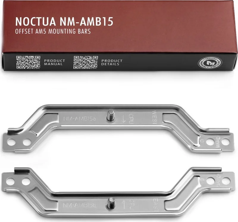
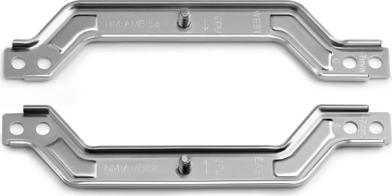
The bar labeled WEST goes on the left side of the socket and the bar labeled EAST goes on the right side to ensure correct orientation.
Is this answer helpful?
Advantages and Disadvantages
Advantages

- Provides specific offset positioning for AM5 and Ryzen 5000 series compatibility
- Clear WEST and EAST markings prevent installation errors
- Supports both AM5 and AM4 socket generations
Disadvantages

- Spacers and long screws are not included with the product
- Standard position only available if clearances are sufficient
- Torque limit of 0 6 Nm requires careful manual handling
Product Specification
Type
Assembly kit
Product Description
Achieving Optimal Thermal Performance on AMD Platforms
Understanding the Noctua NM-AMB15 Offset System
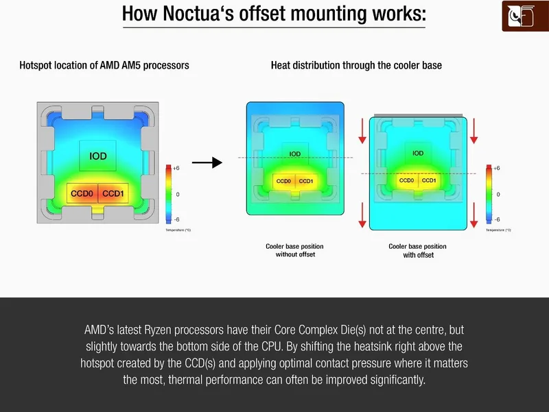
When building a high performance PC, the interface between the processor and the cooler is critical for stability and longevity. The Noctua NM-AMB15 offset mounting bars provide a specialized solution for users requiring enhanced compatibility with AMD Socket AM5 and AM4 motherboards. By adjusting the mounting height, you can ensure better contact and airflow management around the CPU socket area. This hardware modification is essential for Ryzen 5000 and 3000 series processors where standard mounting might cause slight clearance problems or interfere with motherboard heatsinks nearby.
The installation process involves careful attention to alignment and torque specifications to prevent hardware damage. You must distinguish between the two available positions based on your specific motherboard layout and clearance requirements. The offset position lowers the cooler by seven millimeters relative to the standard position of zero millimeters. This drop is often necessary to prevent interference with nearby VRM heatsinks or capacitors located on the motherboard surface. If you are unsure about clearance, check the motherboard documentation first. The standard position remains an option if the offset causes physical conflicts with surrounding components or blocks installation.
Markings on the bars guide the orientation during assembly to ensure even pressure distribution. The NM-AMB15a bar features a WEST marking and belongs on the left side of the socket for proper orientation. The NM-AMB15b bar has an EAST marking and goes on the right side. Incorrect orientation can lead to uneven pressure on the integrated heat spreader which may damage the silicon. Secure the bars using the provided screws but do not tighten them excessively or forcefully. The maximum recommended torque is 0 6 Nm to avoid damage to the mounting bracket or the motherboard PCB itself.
Certain components required for a complete setup are not included in the purchase box to keep costs low. You need four NM-APS4 grey plastic spacers and four NM-ALS1 long screws to finish the job correctly. If replacing an existing cooler, you must remove the old hardware first. Unscrew the original mounting bars from the backplate before proceeding with the new installation procedure properly. For bare boards, remove the retention module and place the spacers over the threads. Once the hardware is secure, apply thermal paste according to the cooler instructions to ensure best results. This step ensures efficient heat transfer from the silicon to the metal surface effectively. Proper spacing allows the fan assembly to sit without stress or vibration. Following these guidelines guarantees a robust connection that minimizes noise and maximizes cooling potential for your system. Always verify compatibility to ensure a smooth upgrade experience without delays or returns from the store. Access guides via mobile code if needed for additional details.
Search for 67,706 Manuals online


Type-in Brand or Model