
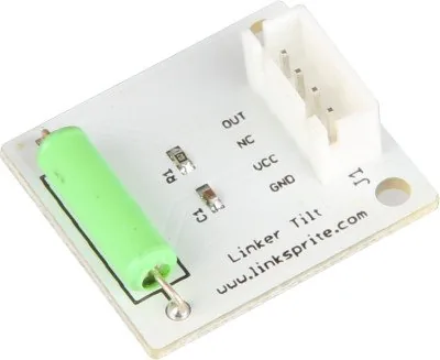
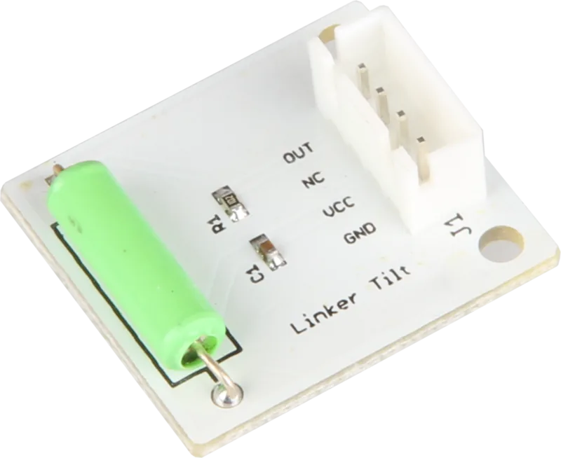
LinkerKit Tilt Module Manual
PDF manual · 2 Pages
English



Quick check
Incorrect answer, please try again.
Chat with your LinkerKit Tilt Module manual using AI
Get instant AI answers from your LinkerKit Tilt Module manual
Ask anything about the LinkerKit Tilt Module. Answers come from this manual, with the pages they are based on.
Ask a Question
Do you recommend Tilt Module?
Yes NoVideo Manual
How To CUT, EXTEND and CONNECT LED Strips
Frequently Asked Questions
It uses two small conductive balls inside the housing that complete a circuit when upright. When tilted, the balls separate and the circuit opens, producing a LOW reading on the signal pin; upright produces a HIGH.
Is this answer helpful?
Connect the SIG (signal) pin to a digital input pin on your microcontroller. NC is not used on this kit. Use an internal or external pull-up/pull-down as appropriate for your logic.
Is this answer helpful?
No. The sensor behaves like a simple switch. Configure the microcontroller pin as INPUT and use digitalRead (or equivalent) to read HIGH or LOW.
Is this answer helpful?
No. It provides only binary state information (tilted or not tilted). For precise angular readings, use an accelerometer or inclinometer.
Is this answer helpful?
Implement software debouncing or filtering (e.g., read multiple samples and use a majority or time threshold) to mitigate chatter caused by vibration or mechanical bounce.
Is this answer helpful?
The basic mechanical design may be susceptible to moisture and contaminants. For harsh environments, consider sealed or solid-state sensors with specified environmental ratings.
Is this answer helpful?
Advantages and Disadvantages
Advantages

- Simple binary output that acts like a momentary switch for easy integration.
- No special drivers required—works with digitalRead and basic GPIO setup.
- Low cost and compact, suitable for many DIY and educational projects.
- Mechanically robust and energy efficient when used as a passive input.
Disadvantages

- Provides only two-state detection; no precise angle measurement.
- Mechanical contacts can chatter under vibration without debouncing.
- Limited environmental tolerance compared to sealed inertial sensors.
Product Specification
Manufacturer
LinkSprite
Type
Tilt sensor
Platform
LinkerKit
Connectivity
1x LinkerKit connection
Power supply
via Host
Dimensions (WxHxD)
1.10x0.42x1.00in
Product Description
LinkerKit Tilt Sensor Manual — Overview
The LinkerKit Tilt Sensor is a simple and reliable digital tilt module that behaves like a momentary switch. Inside the sensor, a pair of conductive balls completes a circuit when the module is upright; when tilted, the balls separate and the circuit opens. Wired to a SIG (signal) line, the sensor provides a binary HIGH/LOW digital input useful for motion detection, orientation sensing, and basic user interaction in DIY electronics projects.
How it works
The core principle is mechanical: two small metal balls act as the contact elements. When the enclosure is aligned upright, the balls settle and bridge the internal contacts, registering a HIGH on the signal pin. When the module tilts beyond a threshold, gravity moves the balls away and the input reads LOW. Because it functions like a button, it integrates easily with microcontroller GPIO pins and can be read with a standard digitalRead call.
Typical uses and projects
LinkerKit’s tilt sensor is ideal for a range of beginner-to-intermediate applications: orientation detection for small robots, rollover detection for toy vehicles, tamper or intrusion alerts, simple game controllers, or as a trigger for LEDs and alarms. It’s a compact, low-cost solution when precise angular measurement isn’t required but reliable binary state detection is.
Quick implementation example
A common pattern is to connect the SIG pin to a digital input on an Arduino and read the state in loop(). When the input is HIGH, an output pin (for example, an LED) can be driven. The sensor needs no special drivers—just pinMode for input and digitalRead in the loop. This makes prototyping and troubleshooting straightforward for newcomers.
Design considerations
The sensor’s mechanical nature means it’s robust and power-efficient (no continuous current draw when used as an input). However, it provides only two-state information (tilted or not tilted) rather than angular precision. Debouncing or simple software filtering may be useful in noisy or vibrating environments. Placement and orientation on the device are important to ensure the tilt threshold matches the intended behavior.
Notes
- Connect SIG to a digital input; NC (normally closed) is not used on this kit.
- Use simple pull-up or pull-down configuration as needed by your microcontroller.
- Add software debounce if the application experiences chatter or vibration.
Search for 67,706 Manuals online


Type-in Brand or Model