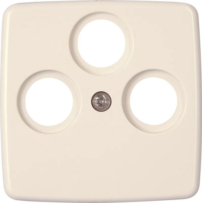
Manual.ly Logo

Kopp RIVO Manual

0.0 · 0 Ratings

PDF manual · 2 Pages

English

M: gpt-5.6-terra
page

/ 2

Loading...
6b2960bae72cecf4cf74adee9248cbe96d8b page 1
D
AAnnlleeiittuunngg AAnntteennnneennsstteecckkddoossee
TTVV//RRFF
AAllss DDuurrcchhggaannggss-- ooddeerr EEiinnzzeell((EEnndd))ddoossee zzuu vveerrwweennddeenn iinn::
- Einzel- und Gemeinschaftsanlagen
(auch mit Verstärker)
- Breitband-Kabelanlagen
Montage / Anschluß:
RReeggeellnn ddeerr EElleekkttrrootteecchhnniikk bbeeaacchhtteenn !!
- Abdeckung abschrauben
- Doppelklemmschelle aufschrauben und aufklappen
- Klemmschrauben der Innenleiter öffnen
- Antennenkabel vorsichtig abisolieren (Abb. 2)
- Antennenkabel nach Anwendung einstecken:
Abb. 3 = Durchgangsdose
Abb. 4 = Enddose mit Abschlußwiderstand (
ΩΩ
)
(
↑↑
) Kabeleingang - (
↓↓
) Kabelausgang
Beachten: Kabeleingangs-/ausgangsklemmen sind
programmvariabel links oder rechts.
- Klemmschrauben der Innenleiter zuschrauben
- Doppelklemmschelle zuklappen und zuschrauben
- Antennensteckdosen-Sockel in Schalterdose
einsetzen, ausrichten und festschrauben
- Rahmen und Abdeckung aufdrücken und
anschrauben (Abb.1)
Schirmungsmaß:
0,1 - 450 MHz > 75 dB; 470 - 860 Mhz > 65 dB
Impedanz: 75 Ohm, Dämpfungswerte siehe oben
D = Durchgangsdämpfung,
A = Anschlußdämpfung
Technische Änderungen vorbehalten.
058 325 010 /
1122 -- 11
UA
ІІннссттррууккццііяя ддлляя ааннттееннннооїї ррооззееттккии
ТТББ//РРааддііоо..
ВВииккооррииссттооввууєєттььссяя яякк ппррооххііддннаа ааббоо яякк ссааммооссттііййннаа ((ккііннццеевваа))
ррооззееттккаа вв::
- окремих або спільних пристроях (також з посилювачем)
- кабельних пристроях широкого діапазону
Монтаж / підключення:
ДДооттррииммууййттеессяя ппррааввиилл ееллееккттррооттееххн
нііккии!!
- відкрутіть кришку
- відпустіть зажимні гвинти внутрішніх провідників
. обережно зніміть ізоляцію з кабеля (рис.2)
. всавте кабель антени згідно з використанням:
Рис. 3 = Прохідна розетка
Рис. 4 = Кінцева розетка з опорем на кінці (
ΩΩ
)
(
↑↑
) Кабельний вхід - (
↓↓
) кабельний вихід
Увага: Кабельні вхідні/вихідні клеми можут, згідно з програм-
ою вимикачи и розеток знаходитися, вліво або вправо.
- прикрутіть зажимні гвинти внутрішніх провідників
- двойну зажимну клему затягніть і закрутіть гвинти
- вставте цокол розетки антени до монтажної коробки,
вирівняйте і прикрутіть.
- Раму і кришку притисніть і прикрутіть (рис.1).
Діапазон екранування:
0,1 - 450 МГц > 75 дБ; 470 - 860 МГц > 65 дБ
Опір: 75 Ом, значення затухання дивись вище
D = затухання у прохідному напрямку, A = затухання
підключення
Виробник залишає за собою право на технічні зміни.
E
IInnssttrruucccciioonneess ppaarraa llaa ccaajjaa ddee eenncchhuuffee ppaarraa
aanntteennaass ddee TTVV//RRaaddiioo
AA eemmpplleeaarr ccoommoo ccaajjaa ddee eenncchhuuffee ddee ddeessvviiaacciióónn oo iinnddiivviidduuaall ((tteerr--
mmiinnaall)) eenn::
- Instalaciones de antena individuales y colectivas
(tam bién con amplificador)
- Instalaciones de televisión por cable de banda ancha
Montaje / Conexión:
OObbsseerrvvaarr llaass rreeggllaass ddee llaa eelleeccttrrootteeccnniiaa!!
- Desenroscar (abrir) la cubierta
- Desenroscar (abrir) el tornillo de fijación de la abrazadera de
sujeción doble y abrirla
- Desenroscar (abrir) los tornillos de los conductores interiores
- Quitar cuidadosamente el aislamiento del cable de la antena
(fig.2)
- Insertar el cable de la antena según la aplicación:
Fig. 3 = Caja de enchufe de desviación
Fig. 4 = Caja de enchufe terminal con resistencia terminal (
ΩΩ
)
(
↑↑
) Entrada de cable - (
↓↓
) Salida de cable
Observar: Los bornes de entrada / salida de cable se aplican según
variabilidad de programa en la izquierda o derecha.
- Enroscar (cerrar) los tornillos de fijación de los conductores interio-
res. - Cerrar la abrazadera de sujeción doble enroscando el tornillo de
fijación. - Colocar la base de la caja de enchufe de antena en la caja de
interruptor, alinearla y atornillarla. - Presionando correspondiente-
mente, aplicar el marco y la cubierta y atornillar (fig.1)
Factor de blindaje: 0,1 - 450 MHz > 75 dB, 470 – 860 MHz > 65 dB
Impedancia: 75 ohmios, valores de atenuación: ver arriba
D = Pérdida por paso, A = Pérdida por inserción / conexión
Salvo modificaciones técnicas
GB
IInnssttrruuccttiioonn AAeerriiaall SSoocckkeett
TTVV//RRaaddiioo
FFoorr uussee aass tthhrroouugghhppuutt oorr ssiinnggllee eenndd ssoocckkeett iinn::
- single and community systems
(also complete with amplifier)
- wide band cable systems
Assembly / connection:
CCoommppllyy wwiitthh aallll eelleeccttrriiccaall eennggiinneeeerriinngg rreegguullaattiioonnss
!!
- Unscrew cover
- Unscrew and open double clamp
- Open clamp screws of inner conductors
- Carefully strip insulation from aerial cable (Fig. 2)
- Insert aerial cable :
Fig. 3 = throughput socket
Fig. 4 = end socket complete with terminal resistor
((
ΩΩ
))
(
↑↑
) cable entry - (
↓↓
) cable exit
Note: cable entry / output clamps are program variable, left or
right.
- Screw in clamp screws of inner conductors
- Close double clamp and screw down
- Insert aerial socket base into switch box,
align and tighten screws.
- Press on frame and cover, and screw down (Fig.1)
Screening capacity:
0,1 - 450 MHz > 75 dB; 470 - 860 Mhz> 65 dB
Impedance: 75 Ohm, see above for attenuation values
D = throughput attenuation (damping), A = connection attenu-
ation. Subject to technical alterations.
F
NNoottiiccee pprriissee dd’’aanntteennnnee
TTVV//RRaaddiioo
AA uuttiilliisseerr eenn ttaanntt qquuee pprriissee ddee ttrraannssffeerrtt oouu pprriissee
iinnddiivviidduueellllee tteerrmmiinnaallee ppoouurr
- installations individuelles et collectives
(même avec amplificateur),
- installations câble à bande large.
Montage / Branchement :
IImmppéérraattiivveemmeenntt rreessppeecctteerr lleess rrèègglleess ddee ll’’éélleeccttrrootteecchhnniiqquuee !!
- Dévisser le couvercle, dévisser et ouvrir le collier double.
- Desserrer la vis de blocage du conducteur interne.
- Dénuder le câble d’antenne, avec précaution (Fig. 2).
- Enficher le câble d’antenne selon l’application envisagée :
Fig. 3 = prise de transfert
Fig. 4 = prise terminale avec résistance terminale (
ΩΩ
)
(
↑↑
) Entrée de câble - (
↓↓
) Sortie de câble
Tenir compte : les bornes d’entrée / de sortie sont à gauche ou
à droite, selon le programme.
- Resserrer la vis de blocage du conducteur interne.
- Refermer et revisser le collier double.
- Insérer le socle de la prise d’antenne dans le boîtier,
l’aligner correctement et le visser fermement.
- Mettre le cadre et le couvercle en place,et les visser(Fig.1)
Blindage : 0,1-450 MHz > 75 dB; de 470-860 MHz > 65 dB
Impédance : 75 Ohm. valeurs d’affaiblissement voir ci-dessus
D = affaiblissement de transfert, A = affaiblissement de bran-
chement.
Sous réserve de modifications techniques.
RUS
ИИннссттррууккцциияя:: ШШттееппссееллььннааяя ррооззееттккаа ддлляя
ааннттеенннныы TTВВ//РРааддииoo
ППррииммееннееннииее вв ввииддее ппррооххоодднноойй ииллии ооттддееллььнноойй ((ккооннццееввоойй))
ррооззееттккии вв::
- отдельных и коллективных установках (также с усилителем)
- широкополосных кабельных установках
Монтаж / присоединение:
ССооббллююддааййттее ппррааввииллаа ээллееккттррооттееххннииккии !!
- отвинтить крышку
- ослабить винт двойного зажима и открыть зажим
- ослабить зажимные винты внутренних проводников
- осторожно изолировать антенный кабель (рис. 2)
- вставить антенный кабель:
Рис. 3 = Проходная розетка
Рис. 4 = Концевая розетка с нагрузочным сопротивлением
(
ΩΩ
). (
↑↑
) Вход кабеля - (
↓↓
) Выход кабеля
Соблюдайте: В зависимости от серии выключателей и розеток
входные/выходные зажимы кабелей находятся налево или
направо.
- Затянуть зажимные винты внутренних проводников
до отказа. Затянуть двойной зажим и зафиксировать его винт-
ом. Вставить цоколь штепсельной розетки в монтажную коро-
бкуб ориентировать и зафиксиировать его винтом. Установи-
ть и привинтить раму и крышку (рис.1)
Данные экранирования:
0,1 - 450 MГц > 75 дБ; 470 - 860 МГц > 65 дБ
Полное сопротивление: 75 ом, значения затухания см. выше. D
= Затухание в пропускном направлении, A = Затухание присо-
единения.
Производитель оставляет за собой право на техн. изменения.
TV
Radio
ΩΩ
NL
HHaannddlleeiiddiinngg aanntteennnneeccoonnttaaccttddooooss
TTVV//RRAADDIIOO
AAllss ddoooorrlluussddooooss eenn aallss eeiinnddddooooss ttee ggeebbrruuiikkeenn iinn::
- antenne- / CAI-installaties voor radio en TV.
Montage / Aansluiting:
EElleekkttrrootteecchhnniisscchhee vvoooorrsscchhrriifftteenn eenn vvoooorrsscchhrriifftteenn vvaann uuww CCAAII--
lleevveerraanncciieerr iinn aacchhtt nneemmeenn !!
- Afdekplaat afschroeven
- Dubbele klem open schroeven en openklappen
- Klemschroeven van de binnenste geleider openen
- Antennekabel voorzichtig aansnijdenen en ader vrijmaken
(afb. 2)
- Antennekabel volgens toepassing insteken:
afb. 3 = doorlusdoos
afb. 4 = einddoos met afsluitweerstand (
ΩΩ
)
(
↑↑
) kabelingang - (
↓↓
) kabeluit- / doorgang
In acht nemen: kabelingangs-/uitgangsklemmen zijn
programmavariabel links of rechts.
- Klemschroeven van de binnenste geleider dichtschroeven
- Dubbele klem dichtklappen en dichtschroeven
- Antennecontactdoos in de inbouwdoos
plaatsen, uitlijnen en vastschroeven
- Raampje en afdekking opdrukken en aanschroeven (afb.1)
HF-afscherming:
0,1 - 450 MHz > 75 dB; 470 - 860 Mhz > 65 dB
Impedantie: 75 Ohm, Dempingswaarden: zie boven
D = doorgangsdemping, A = aansluitdemping
Technische wijzigingen voorbehouden.
22
11 33
44
Heinrich Kopp GmbH • Alzenauer Str. 68 • 63796 Kahl (Germany)
Internet: http://www.heinrich-kopp.de • E-Mail: vertrieb
@@
heinrich-kopp.de
0,15
- 1,6
LM
-
5,0
- 20
Rück-
weg
0,5
47,0
-68
VHF 1
1,0
87,5
- 108
FM
1,0
111
- 139
Digi-
tion
1,0
125
- 174
USB
1,0
MHz
dB
174 - 230
VHF III
1,0
230 - 300
OSB
1,0
300 - 450
ESB
1,2
470 - 620
UHF IV
1,4
620 - 860
UHF V
1,8
MHz
dB
0,15
- 1,6
LM
-
-
5,0
- 20
Rück-
weg
13,2
13,3
47,0
-68
VHF 1
13,6
13,0
87,5
- 108
FM
13,6
13,0
111
- 139
Digi-
tion
13,6
13,0
125
- 174
USB
-
13,0
MHz
dB
Radio
dB
TV
174 - 230
VHF III
-
13,0
230 - 300
OSB
-
13,0
300 - 450
ESB
-
13,0
470 - 620
UHF IV
-
13,0
620 - 860
UHF V
-
12,3
MHz
dB
Radio
dB
TV
D: A:
⎢⎢ -- 88 -- ⏐⏐-- 22 --⏐⏐ -- 88 -- ⏐⏐

Chat with your Kopp RIVO manual using AI

Get instant AI answers from your Kopp RIVO manual

Ask anything about the Kopp RIVO. Answers come from this manual, with the pages they are based on.

Ask a Question

0/1000

Do you recommend RIVO?

Yes No

Frequently Asked Questions

A

It is used to connect TV and radio equipment to coaxial antenna or broadband cable systems. It can serve in individual homes, shared antenna installations, systems with amplifiers, and wide-band cable setups.

Is this answer helpful?

A

Yes. In throughput mode, the incoming cable is connected and the signal can continue through the outlet to another point in the installation. This is useful for chained outlet layouts.

Is this answer helpful?

A

Yes. It can be configured as an end socket. In this application, a terminal resistor is required to properly terminate the cable line.

Is this answer helpful?

A

The specified impedance is 75 Ohm. This is the standard impedance commonly used for TV, radio, antenna, and cable coaxial systems.

Is this answer helpful?

A

The stated screening capacity is greater than 75 dB from 0.1 to 450 MHz and greater than 65 dB from 470 to 860 MHz. This helps limit unwanted external signal interference.

Is this answer helpful?

A

No. The cable entry and exit clamps can be positioned on the left or right depending on the switch and socket program. Check the layout before connecting the cable.

Is this answer helpful?

M: gpt-5.6-terra

Advantages and Disadvantages

Advantages

  • Supports both throughput and terminal outlet configurations for flexible cable layouts.
  • Compatible with individual, community, amplified, and broadband cable antenna systems.
  • 75 Ohm impedance suits common TV and radio coaxial installations.
  • Strong screening performance exceeds 75 dB up to 450 MHz and 65 dB up to 860 MHz.
  • Double clamp design helps secure the aerial cable during installation.
VS

Disadvantages

  • Correct terminal resistor selection is required when used as an end socket.
  • Installation requires careful cable stripping and secure inner conductor connections.
  • Attenuation differs by frequency and configuration, so planning is necessary.
  • Electrical installation rules must be followed during fitting.
  • Cable terminal orientation can vary by the selected switch and socket program.
M: gpt-5.6-terra

Product Description

Kopp RIVO - Read, Download & Print Free

The Kopp RIVO TV/Radio aerial socket is a practical installation component for reliable signal distribution in residential and shared antenna systems. Designed for TV and radio connections, it supports both through and end-point configurations, making it suitable for flexible setups in homes, apartments, and broadband cable installations. Its 75 Ohm impedance aligns with common coaxial signal systems and helps maintain dependable reception across a broad frequency range.

Built for adaptable antenna installations

Kopp RIVO can be configured as a throughput socket when a cable must continue to another connection point, or as an end socket when the line terminates at the outlet. The end configuration uses a terminal resistor to support correct operation. This adaptability can simplify planning where several TV or radio outlets share one cable route.

The cable entry and exit terminals may be positioned on the left or right depending on the selected switch and socket program. This detail supports cleaner routing inside the mounting box and helps installers adapt the connection to the available space.

Clear connection concept

The installation approach is straightforward: remove the cover, open the double clamp, prepare the aerial cable carefully, and secure the inner conductor with the clamp screws. After the cable is fastened, the socket base is aligned in the switch box before the frame and cover are fitted. The double clamp is intended to hold the cable securely and support a stable installation.

Electrical engineering rules must be observed during fitting. Careful stripping and correct conductor placement are especially important, as poorly prepared coaxial cable can affect signal quality or create unreliable connections.

Signal protection across key bands

The socket provides screening performance of more than 75 dB from 0.1 to 450 MHz and more than 65 dB from 470 to 860 MHz. This shielding helps reduce the influence of unwanted external signals across relevant radio, VHF, UHF, and cable frequency ranges. The stated attenuation values vary by frequency and by selected use as a through or terminal connection.

Notes

  • Select the correct throughput or end configuration before wiring.
  • An end installation requires the appropriate terminal resistor.
  • Verify cable entry and exit orientation before tightening the clamps.
  • Technical specifications may be changed by the manufacturer.

Kopp RIVO - Read, Download & Print Free is a useful reference phrase for anyone comparing a versatile TV/Radio aerial outlet designed for organized, shielded coaxial installations.

M: gpt-5.6-terra

© Copyright 2026 Manual.ly