Manual.ly Logo

Kopp Paris Manual

0.0 · 0 Ratings

PDF manual · 2 Pages

English

M: QW-35-FL
page

/ 2

Loading...
e9a435844502eae20d9351b8feb8223ccc97 page 1
D
Anleitung Antennensteckdose
TV/RF/SAT
Als Einzel(End)dose u. Stichleitungsdose zu verwenden in:
- Einzelanlagen
- entkoppelte Stichleitungen in SAT- und Kabel-TV-
Anlagen
Montage / Anschluß:
Regeln der Elektrotechnik beachten !
- Abdeckung abschrauben
- Klemmschraube der Masseschelle öffnen
- Schraube des Innenleiters öffnen (teilweise Steck-
klemmen)
- Antennenkabel vorsichtig abisolieren (Abb. 2)
- Antennenkabel einstecken (Abb. 3):
(á-) Kabeleingang - (â) nicht belegt
Beachten: Innenleiter-Klemmschraube bzw.
Steckklemme programmvariabel links oder rechts.
- Klemmschrauben der Innenleiter zuschrauben bzw.
Innenleiter einstecken
- Masseschelle zuschrauben
Bei Einsatz einer Satellitenschüssel und einer terristischen
Antenne, ist eine Trennweiche einzusetzen (s. Abb. 4)
- Antennensteckdosen-Sockel in Schalterdose einset-
zen, ausrichten und festschrauben
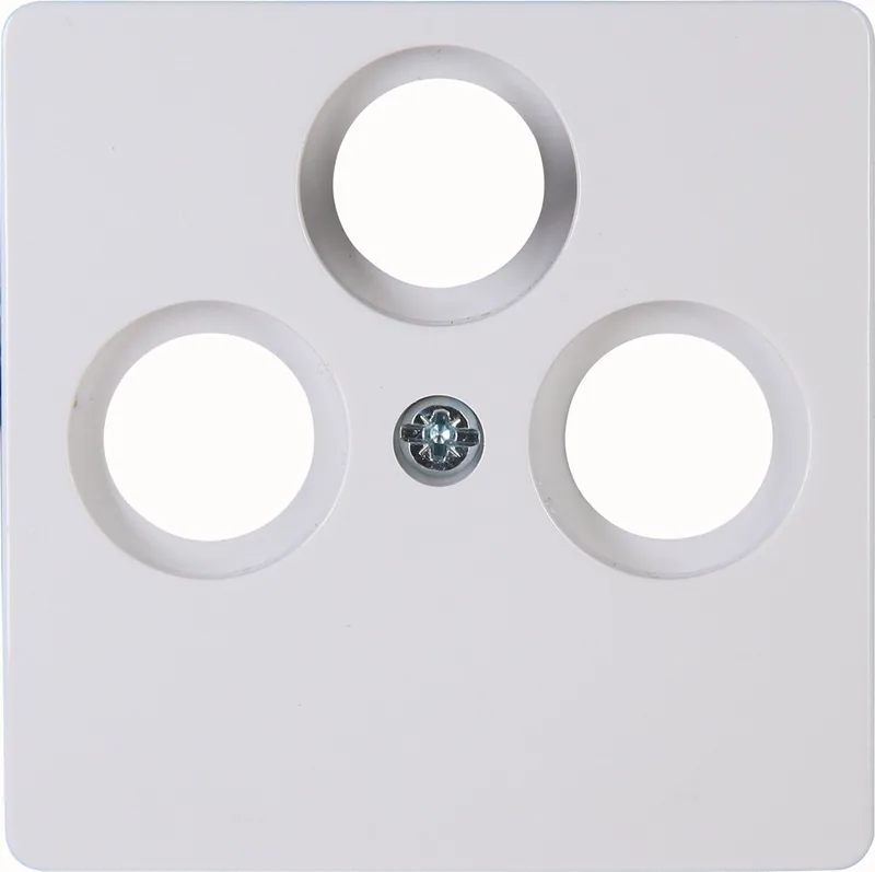
- Rahmen und Abdeckung aufdrücken und anschrauben
(Abb. 1)
Schirmungsmaß:
100 MHz > 75 dB; 470 Mhz > 65 dB
Impedanz: 75 Ohm
Frequenzbereiche und Anschlußdämpfung siehe oben
Technische Änderungen vorbehalten.
G
Instruction Aerial Socket
TV/Radio/SAT
For use as single end socket and stub socket in:
- single user systems
- de-coupled stubs in SAT and cable TV systems
Fitting / Connection:
Comply with all electrical engineering regulations !
- Unscrew cover
- Open clamp screw of ground clamp
- Undo screw of inner conductor ( partly, plug clamps)
- Carefully strip insulation from aerial cable (Fig. 2)
- Insert aerial cable (Fig. 3):
(á-) Cable input - (â) not in use
Note: inner conductor clamp screw or plug clamp is
program variable, left or right.
- Screw in clamp screw of inner conductors or insert
inner conductor
- Screw in ground clamp
If a satellite dish and a terrestrial aerial are used, diplxing
filter is to be used (see Fig.4)
- Insert aerial socket base into switch box, align and
tighten screws.
- Press on frame and cover, and screw down (Fig. 1)
Screening capacity:
100 MHz > 75 dB; 470 Mhz > 65 dB
Impedance: 75 Ohm.
For frequency ranges and connection attenuation see
above.
Subject to technical alterations.
O
Handleiding antennecontactdoos TV/Radio/SAT
Als doorlusdoos en als einddoos te gebruiken in:
- antenne- / SAT-installaties voor radio en
satellietprogramma’s.
Montage / Aansluiting:
Elektrotechnische voorschriften en voorschriften van uw
CAI-leverancier cq. satellietleverancier in acht nemen !
- Afdekplaat afschroeven
- Klemschroef van de massaklem openen
- Schroef van de binnenste geleider openen (gedeeltelijk
steekklemmen)
- Antennekabel voorzichtig aansnijdenen en ader
vrijmaken (afb. 2)
- Antennekabel insteken (afb.3):
(á-) kabelingang - (â) niet bezet
In acht nemen: Binnenste geleider-klemschroef resp.
steekklem programmavariabel links of rechts.
- Klemschroeven van de binnenste geleider
dichtschroeven resp. binnenste geleider insteken
- Massaklem dichtschroeven
Bij gebruik van een schotelantenne en een terristische
antenne, moet er een scheidingsfilter worden gebruikt
(zie afb. 4)
- Antennecontactdoos in de inbouwdoos plaatsen,
uitlijnen en vastschroeven
- Raampje en afdekking opdrukken en aanschroeven
(afb.1)
HF-afscherming: 100 MHz > 75 dB; 470 Mhz > 65 dB
Impedantie: 75 Ohm. Frequentiebereik en dempingswaar-
den zie boven. Technische wijzigingen voorbehouden.
F
Notice prise d’antenne TV/Radio/SAT
A utiliser en tant que prise individuelle terminale ou prise
de branchement pour
- installations individuelles
- lignes de dérivation découplées sur les installations de
TV câble et satellite
Montage / Branchement:
Impérativement respecter les règles de l’électrotechnique !
- Dévisser le couvercle.
- Desserrer la vis de blocage du collier de masse.
- Desserrer la vis de blocage du conducteur interne
(broches à enficher, en partie).
- Dénuder le câble d’antenne, avec précaution (Fig. 2).
- Enficher le câble d’antenne (Fig. 3):
(á-) Entrée de câble - (â) libre
Tenir compte: la vis de blocage du conducteur interne
ou la broche à enficher est à gauche ou à droite, selon le
programme.
- Resserrer la vis de blocage du conducteur interne ou
enficher le conducteur interne.
- Resserrer le collier de masse.
A la mise en œuvre d’une parabole satellite et d’une
antenne terrestre, prévoir un diplexeur (voir Fig. 4).
- Insérer le socle de la prise d’antenne dans le boîtier,
l’aligner correctement et le visser fermement.
- Mettre le cadre et le couvercle en place, et les visser
(Fig. 1)
Blindage: 100 MHz > 75 dB; 470 MHz > 65 dB
Impédance: 75 Ohm.
Gammes de fréquences et affaiblissement de branche-
ment, voir cidessus.
Sous réserve de modifications techniques.
T
Anten prizi kullanma talimatı
TV/Radio/SAT
- Tekli tesisatlarda
- Uydu ve kablolu televizyon tesisatlarında ayrılmış
Tekli (son) priz veya reaktans prizi olarak kullanımı
Montajı / Bağlantısı:
Elektroteknik kurallarına uyunuz!
- Kapağı çıkarınız
- Toprak kelepçesinin sıkıştırma vidasını açınız
- İç akım kablosunun vidasını açınız (Sıkıştırma yayı)
- Anten kablosunun izolasyonunu itina ile açınız (Resim
2)
- Anten kablosunu sokunuz (Resim 3):
(á-) Kablo girişi - (â) boş
Dıkkat: İç akım kablosunun sıkıştırma vıdası veya
sıkıştırma yayı programa göre sol veya sağ olarak
değişkendir.
- İç akım kablosunun sıkıştırma vidalarını sıkıştırınız
veya İç akım kablosunu sokunuz
- Toprak kelepçesini vidalayınız
Uydu anteni veya teristik anten kullanılması halinde bir
ayırma tertibatı kullanılması gerekirç (Resim 4)
- Anten prizi tabanını şalter yuvasına yerleştiriniz,
ayarlayınız ve vıdalayarak sıkıştırınız. (Resim 1)
Koruma ölçüsü:
100 MHz > 75 dB; 470 Mhz > 65 dB
Empedans: 75 Ohm.
Frekans alanları va Bağlantı sönümü için yukarıya bakınız.
Teknik değişiklik yapma olasılığı sakıdır.
E
Instrucciones para la caja de enchufe para antenas de
TV/Radio/SAT
A emplear como caja de enchufe individual (terminal) y
caja de línea de adaptación en:
- Instalaciones de antena individuales
- Líneas de adaptación aisladas en instalaciones de
TV por SAT y por cable
Montaje / Conexión:
Observar las reglas de la electrotecnia!
- Desenroscar (abrir) la cubierta
- Desenroscar (abrir) el tornillo de fijación para abrir la
abrazadera de puesta a tierra
- Desenroscar (abrir) el tornillo del conductor interior
(en parte bornes enchufables)
- Quitar cuidadosamente el aislamiento del cable de la
antena (fig. 2)
- Insertar el cable de la antena (fig. 3):
(á-) entrada de cable - (â) no ocupada
Observar: Tornillo de fijación de conductor interior resp.
borne enchufable según variabilidad de programa izquier-
da o derecha.
- Enroscar (cerrar) los tornillos de fijación de los conduc-
tores interiores resp. insertar el conductor interior.
- Cerrar la abrazadera de puesta a tierra enroscando el
tornillo de fijación Si se emplea una antena parabólica
y una antena terrestre, se tiene que emplear una
bifurcación de separación (véase la fig. 4)
- Colocar la base de la caja de enchufe en la caja de
interruptor, alinearla y aplicar la cubierta presionando
correspondientemente (fig. 1)
Factor de blindaje:
100 MHz > 75 dB; 470 MHz > 65 dB
Impedancia: 75 ohmios;
Gamas de frecuencia: ver arriba
Salvo modificaciones técnicas
Q
Instrukcja gniazda antenowego
TV/Radio/SAT
Zastosowanie; jako gniazdo końcowe
- instalacjach indywidualnych lub zbiorczych
- instalacjach telewizji kablowej i satelitarnej
Montaż / Podłączenie:
Należy przestrzegać zasad pracy z urządzeniami elektro-
technicznymi!
- po odkręceniu śrub zdjąć pokrywę
- zwolnić śrubę mocującą uchwytu
- odkręcić śrubę wewnętrznego przewodu
- zdjąć ostrożnie izolację z kabla antenowego (rys. 2)
- wetknąć kabel antenowy (rys. 3):
(á-) Wejście kablowe - (â
) nie zajęte
Uwaga: Śruba mocująca wewnętrznego przewodu, ew.
zacisk w zależności od programu wyłączników i gniazd
może znajdować się z prawej lub z lewej strony.
- śruby mocujące wewnętrznych przewodów dokręcić,
ew. wetknąć wewnętrzne przewody
- dokręcić uchwyt mocujący
Sygnał z anteny satelitarnej i anteny do odbioru naziem-
nego należy doprowadzić do sumatora (rys. 4)
Mechanizm gniazda antenowego włożyć do puszki
instalacyjnej, wyrównać i dokręcić śruby.
- ramkę i pokrywę docisnąć i przykręcić (rys. 1)
Zakres tłumienia:
100 MHz > 75 dB; 470 MHz > 65 dB
Impedancja: 75 Ohmów.
Zakresy częstotliwości oraz tłumienie przyłączeniowe
zobacz powyżej.
Zmiany techniczne zastrzeżone.
MHz
Rückkanal
4 - 30
VHF B.1
47 - 68
FM UKW
87,5-108
dB Radio
< 1
TV
< 1
Radio
< 1,5
MHz FM SAT
108 -
125
VHF
139 -
470
UHF
470 -
860
SAT-ZF
950 -
2400
dB Radio
< 3
TV
< 1,5
TV
< 3
SAT
< 2
Heinrich Kopp GmbH • Alzenauer Str. 68 • 63796 Kahl am Main
Internet: http://www.kopp.eu • E-Mail:vertrieb@kopp.eu
43
SAT
Radio
1
-8- -2- -8-
DU09100184 / 058 328 010 / 13 - 1

Chat with your Kopp Paris manual using AI

Get instant AI answers from your Kopp Paris manual

Ask anything about the Kopp Paris. Answers come from this manual, with the pages they are based on.

Ask a Question

0/1000

Do you recommend Paris?

Yes No

Frequently Asked Questions

A

The Kopp Paris is a dual-purpose antenna socket designed for TV and radio. It functions effectively as a pass-through connector to link multiple devices or as a terminal socket with a built-in resistor to end a cable run.

Is this answer helpful?

A

Yes, the Kopp Paris is explicitly designed for use in both individual and community antenna systems. It works well even in setups that include signal amplifiers.

Is this answer helpful?

A

It supports a wide bandwidth from 0.1 MHz up to 860 MHz. Shielding efficiency is greater than 75 dB for the lower range and greater than 65 dB for the higher range.

Is this answer helpful?

A

You must unscrew the double clamp, open it, insert the stripped cable, tighten the inner conductor screws, close the clamp, and secure it. Note that clamps can be positioned left or right depending on the program.

Is this answer helpful?

A

The impedance is 75 Ohms, which is the standard requirement for most television and radio coaxial cable installations.

Is this answer helpful?

A

Yes, when used as a terminal socket (end socket), it includes a built-in termination resistor to prevent signal reflection and ensure proper reception.

Is this answer helpful?

M: QW-35-FL

Advantages and Disadvantages

Advantages

  • Versatile usage as both pass-through and terminal socket
  • High shielding capacity exceeding 75 dB in lower frequencies
  • Compatible with single and community antenna systems
  • Flexible clamp positioning for left or right cable entry
  • Standard 75 Ohm impedance ensures broad compatibility
VS

Disadvantages

  • Requires careful stripping of cable insulation during install
  • Double clamp mechanism may require extra tightening time
  • Not suitable for non-standard frequency ranges beyond 860 MHz
  • Installation requires adherence to specific electrical rules
  • Terminal resistor value must be matched correctly for end-use
M: QW-35-FL

Product Description

Experience Crystal Clear Signals with Kopp Paris

Unlock the full potential of your home entertainment system with the Kopp Paris antenna socket, a versatile solution designed for modern TV and radio installations. Whether you are setting up a single household connection or managing a complex community network, this product ensures reliable performance across a wide frequency range. The Kopp Paris is engineered to handle both individual setups and shared systems, including those equipped with signal amplifiers, making it an ideal choice for diverse residential and commercial environments.

Designed with precision, the Kopp Paris adapts seamlessly to broadband cable networks. Its robust construction guarantees high shielding effectiveness, protecting your signal from interference in the critical 0.1 to 450 MHz and 470 to 860 MHz bands. This level of protection ensures that every channel remains crisp and every broadcast stays clear. The unit features a standard 75 Ohm impedance, aligning perfectly with industry standards for optimal signal transmission and minimal loss.

Installation is straightforward when following basic electrical engineering guidelines. The device offers flexible configuration options, allowing users to utilize it as either a pass-through socket for daisy-chaining connections or as a terminal end-point with a built-in termination resistor. This adaptability simplifies wiring layouts, whether you need to extend a signal through multiple outlets or terminate a line at the final destination. The program-variable clamps can be configured on the left or right side, providing flexibility during installation to match existing switch boxes and wall plates.

The Kopp Paris represents a commitment to quality and durability. By integrating advanced shielding technology, it minimizes attenuation, ensuring that your audio and video experiences remain uninterrupted. The design accommodates various mounting scenarios, fitting securely into standard switch boxes with a frame and cover that provide a clean, professional finish. With its focus on ease of use and superior technical specifications, the Kopp Paris stands out as a premium choice for anyone seeking reliable connectivity for their television and radio equipment.

M: QW-35-FL

© Copyright 2026 Manual.ly