Manual.ly Logo

Kindermann Comfort2 10 Manual

0.0 · 0 Ratings

PDF manual · 2 Pages

English

M: OA-GPT-5-NAN
page

/ 2

Loading...
554f8e8e24adeb341157ac642eb3a1f4de23 page 1
Seite / Page / Page 6 Seite / Page / Page 7 Seite / Page / Page 8 Seite / Page / Page 9
Seite / Page / Page 10 Seite / Page / Page 11 Seite / Page / Page 12 Seite / Page / Page 13
Montage
a
a
a
b
b
b
b
Säule
Überprüfen Sie zuerst den Standort der Deckenhalterung nach Bildgrößen-
tabelle und Keystone-Winkel des Projektors.
Führen Sie eine Testprojektion durch.
Befestigen Sie über geeignete Halteschrauben und Dübel die Säule
am
festgelegten Standort.
a
Langlöcher für Deckenmontage
b
Bohrungen für die Anbringung von Trägerklemmen (Nr. 5873000000) zur
Montage an Rundrohr-Traversen.
Beachten Sie dabei die Lage der ankommenden Verbindungskabel zur innen-
liegenden Kabelführung.
Beachten Sie bitte die Sicherheitshinweise!
Mounting
Column
Choose the location of the ceiling fixture according to the picture size chart
and the Keystone correction of your projector.
If in doubt, test the projection.
Fix the column
at the proper location with suitable holding screws and
plugs.
a
Long holes for ceiling mounting
b
Drill holes for fixing the clamps (No. 5873000000) when mounting the
unit on tube-shaped supports.
Make sure that the connection cables can be inserted into the integrated
cable channel.
Observe the safety instructions!
Montage
Colonne
Vérifier le positionnement de la potence plafond selon la tabelle de grosseur
d’image et l’angle de correction Keystone du projecteur.
Faire un test de projection.
Fixer à l’aide de vis et de chevilles appropriées la colonne
à l‘endroit
déterminé.
Schnellwechsel-
vorrichtung
Quick exchange of
projector
Système de pose pour
changement rapide
Gelenk für 3D-Neigung
Joint for 3D tilting
Articulation
d´inclinaison 3D
Abstandsbolzen
einstellbar
Adjustable distance
elements
Boulons d´écartement
ajustables
Schnellübersicht / At one glance / Apperçu
Kabeleintritt
Cable entry
Entrée de câble
Innenliegende Kabelführung,
Absturzsicherung
Integrated cable channel,
crash protection
Passage de câble interne
Sécurité, anti-chute
Stufenlose Teleskop-
höhenverstellung
Stepless telescopic
height adjustment
Hauteur ajustable
télescopique continue
a
Trous allongés pour montage plafond
b
Trous pour l’attache de pinces de portée (N° 5873000000) pour montage
à traverses de scène.
Prenez compte de la position des câbles d‘entrée de raccordement par rap-
port à la conduite interne de câbles.
Faire attention aux consignes de sécurité!
Montage
Projektorhalter
Mit einem 10 mm Gabelschlüssel die Verschraubung
c
des Projektorhalters
lockern, Kontomutter der Gegenseite dabei festhalten. Drehen Sie die vier
Gewindeabstandsbolzen
a
in die Gewindebohrungen der Arme. Sie können
damit unterschiedliche Höhenlagen der Gewindebuchsen Ihres Projektors
ausgleichen. Legen Sie Ihren Projektor mit der Unterseite nach oben auf eine
weiche Unterlage.
Stellen Sie fest, welcher der Schraubensätze
zu den Gewindebuchsen
Ihres Projektors paßt und befestigen damit den Projektorhalter durch die vier
Abstandsbolzen
a
. Setzen Sie dazu beidseitig die passenden U-Scheiben ein
(nicht nötig bei M6).
Es ist darauf zu achten, die Arme so auszurichten, dass der Schwerpunkt des
Projektors möglichst im Aufhängepunkt des Projektorhalters liegt.
Lockern Sie jetzt die beiden Schrauben
b
mit einem Innensechskantschlüssel
(Größe 3 mm), damit Sie die fertig montierte Einheit in die Schnellwechselvor-
richtung der montierten Säule einhängen können. Zum Sichern die Schrauben
wieder anziehen. Zum Abnehmen diese beiden Schrauben wieder lockern und
Projektorhalter seitlich abziehen.
Hinweise
Die beiden Schrauben
b
sind gegen Herausschrauben gesichert und sollten
nicht gewaltsam überdreht werden.
Achten Sie darauf, dass die Lüfterönungen des Projektors frei bleiben!
Mounting
Projector holder
Loosen the fastening screws
c
of the adjustable carrying arms with the
spanner 10 mm. Insert the four distance elements
a
into the drill-holes of
the carrying arms. Thus you can compensate dierent levels of the drill-
holes at the botton of your projector.
Put your data/video projector on a soft surface upside down.
Make sure to choose the proper sets of screws
which fit to your unit
and fasten the projector holder by putting the screws through the distance
elements
a
.
Also use the suitable washers on both sides of the distance elements. Then
fasten the screws of the projector holder
c
. Now loosen the two Allen
head screws
b
with a special screw driver for hollow screws (3 mm) on
the projector holder so that you can fix the pre-mounted unit at the quick-
mounting device of the column.
Secure the construction by fixing the two screws again.
For taking o the projector loosen the two screws and pull o the projector
holder sidewards.
Note:
The two screws
b
are protected against total removal and should not be
turned violently.
Make sure that the ventilation grilles of the projector are unobstructed!
Montage
Support projecteur
Dévisser les vis du support
c
plafond à l’aide de clé ouvertes 10 mm.
Tournez les 4 boulons d’écartement
a
dans le taraudage des bras. Avec
ces boulons vous pouvez compenser les diérentes hauteurs des pieds
The models “Comfort
2
60, Comfort
2
100 and Comfort
2
150” are equipped
with a telescopic column for stepless height-adjustment. For adjustment
loosen the four clamps
a
with a screw driver for hollow screws 2 mm.
Informations générales / Possibilités de réglage
Le domaine d’attaches de votre projecteur doit être entre 75 et 370 mm.
Fixation possible avec seulement 3 bras profilés. Le poids maximum du
projecteur ne doit pas dépasser 20 kg!
En dévissant la vis de bloquage dans le bas de la colonne
, le projecteur
peut être tourné à ±180° et incliné à ±20°. Après l‘ajustage complet
resserrez le vis de fixation
b
avec une clé 10 mm.
Les modèles „Comfort
2
60, Comfort
2
100 et Comfort
2
150“ ont un tube
télescopique avec réglage graduel de la hauteur. Pour régler la hauteur,
dévisser les 4 vis de bloquage à l’aide d’une clé à 6 pans de 2 mm.
Sicherheitshinweise
• Die Befestigung sollte nur von Fachpersonal ausgeführt werden.
• Überzeugen Sie sich in jedem Fall von der ausreichenden Tragfähigkeit
der Decke für Projektor und Deckenhalterung.
• Benutzen Sie nur ausreichend dimensionierte Schrauben, die speziell für
die vorhandene Deckenstruktur geeignet sind.
Diese Schrauben sind nicht im Lieferumfang enthalten!
• Überprüfen Sie, ob das Deckenmaterial die für eine dauerhafte Montage
erforderliche Festigkeit hat.
Geeignete Deckenstrukturen sind: Hartholz – Stahlträger – Beton.
• Führen Sie nach der Montage einen Belastungstest mit der doppelten
Belastung durch.
• Die Befestigungsschrauben für den Projektor müssen mindestens drei
Umdrehungen ins Gewinde (Geräteseite) eingedreht sein
• Sind die Befestigungsschrauben für die Gewindebuchsen Ihres Projek-
tors zu lang, verwenden Sie bitte zusätzliche U-Scheiben, um Beschädi-
gungen im Gerät zu vermeiden.
• Die Abluft des Projektors ist heiß!
Auf ausreichende Belüftung und Abstände zu anderen Materialien
achten. Durch Überhitzung kann das Gerät Schaden nehmen.
• Um Kabelaufwicklungen oder sogar Kabelbrüche zu vermeiden, drehen
Sie den Projektor mit Projektorhalter horizontal nicht weiter als ± 180°.
• Die Anschlusskabel vom Projektor dürfen bei Neuausrichtung keinen
übermäßigen Beanspruchungen ausgesetzt werden!
• Wir haften nicht bei unsachgemäßer Montage und für Folgeschäden.
• Bitte Anleitung aufbewahren.
• Das Herausschrauben der Feststellschraube für die Höhenverstellung
c
ist blockiert. Die Feststellschraube darf keinesfalls mit Kraft völlig heraus-
gedreht werden!
Safety instructions
• The mounting should only be done by qualified personnel.
• Make sure that the construction of the ceiling is suitable for
permanently holding the weight of the projector and the mounting kit.
• Suitable materials to attach the mounting kit to are hard wood, metal or
concrete surfaces.
• Only use the proper screw dimensions which are suitable for the
construction of the ceiling.
Such screws are not included in the mounting kit!
• After mounting the ceiling bracket, test the construction with twice the
weight of the projector.
• Screw the bolts at least three turns into the drill-holes of the projector.
• If the screws are too long for the drill-holes of your projector,
use additional discs in order to prevent damages.
• The airflow of the projector is hot! Make sure that the unit keeps its
distance to other materials and that the flow of fresh air is not
hampered. The projector can be ruined by overheating.
• In order not to roll up the cable or break it, do not turn the projector with
the projector holder more than ± 180° in both directions.
• When altering the position of the projector make sure that the connection
cables are not damaged.
• We are not responsible for subsequent damages in case of incompetent
mounting.
• Please keep this user manual.
• The completely unscrewing of the clamping screw for height adjustment
c
is blocked. Do not release this screw with power for turning out!
Consignes de sécurité
• L’installation doit être uniquement eectuée par du personnel qualifié.
• Vérifier en tout cas la force de tenue du plafond soit susante pour
projecteur et support.
• Utiliser uniquement des vis de grosseur susante, qui sont spécialement
conçues pour le matériel de plafond rencontré.
Ces vis ne sont pas livrées avec le support.
• Vérifier que la solidité de la matière du plafond est convenable pour un
montage définitif et qu’il y a aucun risque de chute.
Les matières de plafonds convenables sont: Bois dur, poutre d’acier,
béton.
• Faites un test de charge du double du poids.
• Les boulons d’attache doivent être tournés au moins trois fois dans le pied
du projecteur.
• Si les vis de montages sont trop longues, il faut utiliser des rondelles
supplémentaires pour ne pas endommager le projecteur.
• Un montage incorrect, un plafond défectueux ou non-convenable sont des
risques potentiels pour personnes, appareil et équipement!
• Le ventilateur du projecteur est chaud! Faites attention aux distances
nécessaires pour la circulation d’air et la distance aux autres matériaux.
L’appareil peut être endommagé à cause de surchaue, ou il peut
prendre feu!
• Pour éviter l’enroulement du câble, ne tourner pas le projecteur à plus de
±180° horizontalement.
• Les câbles doivent être assez longs pour que lors de nouvelle orientation
du projecteur, ils ne subissent pas de tension.
• Nous ne sommes pas responsables en cas de montage non-approprié et
pour des préjudices ultérieurs.
• Les installations électriques ne doivent être faites que par du personnel
compétant.
• Conservez le mode d’emploi.
• Le dévissage complet de la vis de fixation pour le réglage de la hauteur
c
est bloqué. La vis de fixation ne doit en aucun cas être forcée pour la
dévisser complètement!
Rosette zur Verkleidung
des Deckendurchbruchs
mit Verschluss-Stopfen für
Schrauben (alternativ mit
O-Ring)
Collar for covering of ceiling
break-through with closing
plugs for srews (alternatively
with o-ring)
Rosette pour traverse de
plafond (alternative avec
anneau)
Rosette zur Abdeckung
der Deckenplatte
Collar for covering of the
ceiling-plate
Rosette pour pose sur
dalles de faux-plafond

Chat with your Kindermann Comfort2 10 manual using AI

Get instant AI answers from your Kindermann Comfort2 10 manual

Ask anything about the Kindermann Comfort2 10. Answers come from this manual, with the pages they are based on.

Ask a Question

0/1000

Do you recommend Comfort2 10?

Yes No

Frequently Asked Questions

A

The Comfort² 10 provides a fixed distance of 12 cm between the projector and the ceiling, designed for low-profile installations where minimal drop is required.

Is this answer helpful?

A

The mount supports drill-hole patterns with a diameter range from 75 mm to 370 mm and can be used with either three or four adjustable carrying arms to match various projector footprints.

Is this answer helpful?

A

No. The Comfort² 10 does not have a telescopic height adjustment or integrated cable channel; those features are available on larger Comfort² models (60, 100, 150). Cables must be routed externally and secured appropriately.

Is this answer helpful?

A

The maximum supported projector weight is 20 kg. Ensure the ceiling structure and fastening hardware are rated accordingly and that bolts are screwed in at least three turns into the projector's threaded inserts.

Is this answer helpful?

A

Yes. The mount features a 3D joint that allows approximately ±180° horizontal rotation and ±20° tilt, enabling fine alignment of the projected image when combined with projector adjustments.

Is this answer helpful?

A

Installation should be performed by qualified personnel. Verify ceiling load-bearing capacity (hardwood, steel, or concrete recommended), use suitable anchors (not supplied), test the mount with twice the projector weight, keep ventilation clear, and avoid over-rotating to prevent cable strain.

Is this answer helpful?

A

The kit includes the column, rosette, closing plugs, projector holder, distance elements, and screw sets M3/M4/M5/M6 with washers. Required tools typically include a Phillips screwdriver, 10 mm and 7 mm spanners, and a 3 mm Allen key; appropriate ceiling screws/anchors are not included.

Is this answer helpful?

M: OA-GPT-5-NAN

Advantages and Disadvantages

Advantages

  • Compact low-profile design with 12 cm projector-to-ceiling distance
  • Supports 75–370 mm mounting patterns and 3- or 4-arm configurations
  • Quick-exchange mounting interface for easy removal and maintenance
  • Allows ±180° rotation and ±20° tilt for image alignment
  • Supplied with multiple screw sets and distance elements for broad compatibility
VS

Disadvantages

  • No internal cable channel (except larger Comfort² models)
  • Fixed drop height — no telescopic adjustment on Comfort² 10
  • Mounting screws and appropriate ceiling anchors are not included
  • Maximum projector weight limited to 20 kg
  • Installation should be performed by qualified personnel
M: OA-GPT-5-NAN

Product Specification

Type

Ceiling mount

Ceiling distance

4.72in

Tilt angle

20°

Max. load capacity

44.09lb

Color

silver

M: OA-GPT-54-NAN

Product Description

Kindermann Comfort² 10 silber Manual

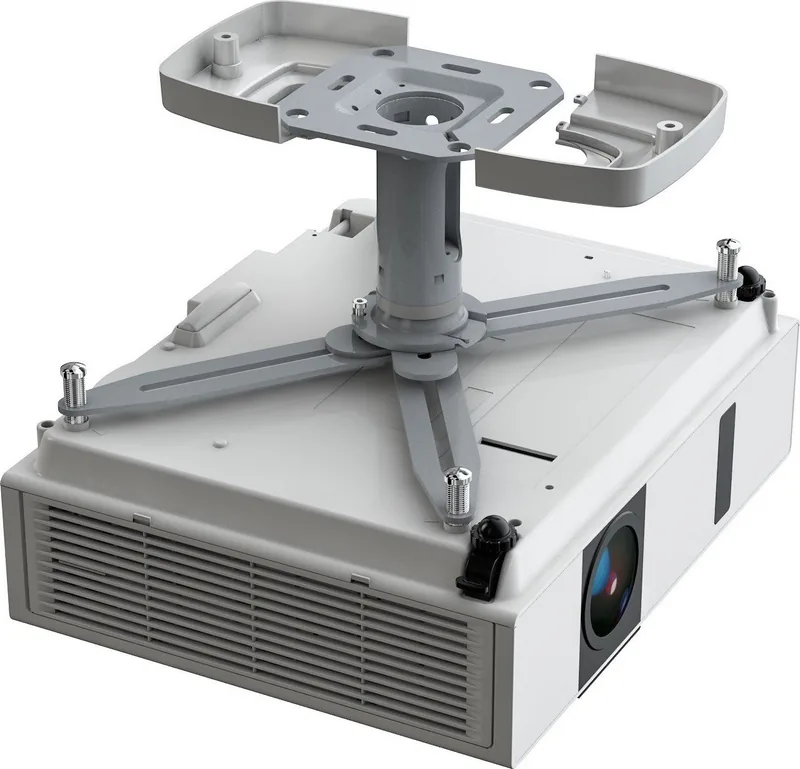
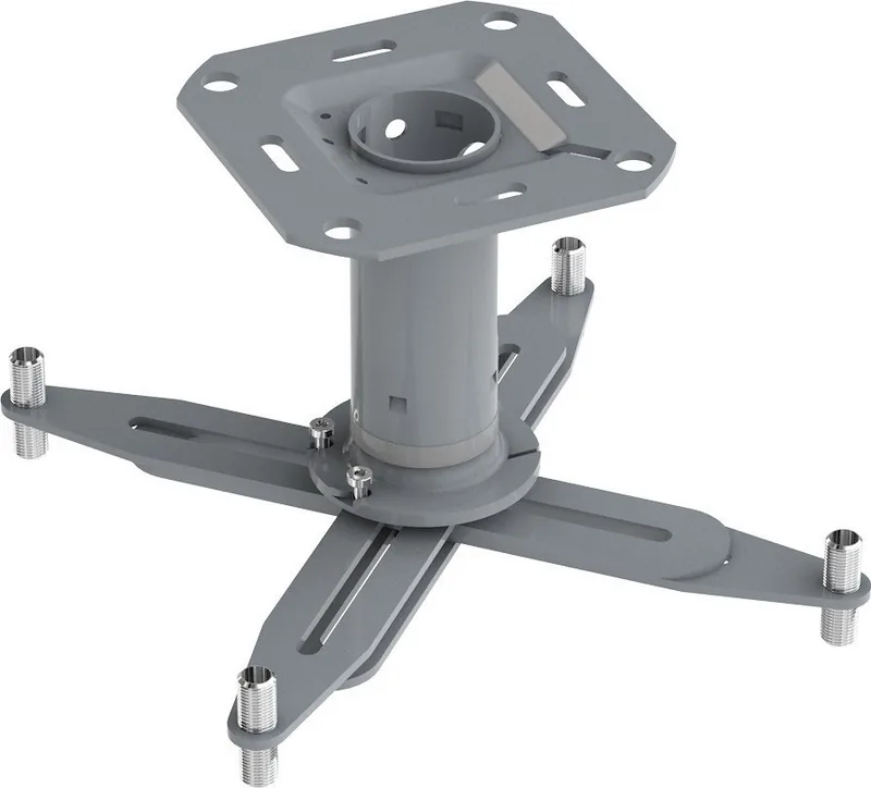
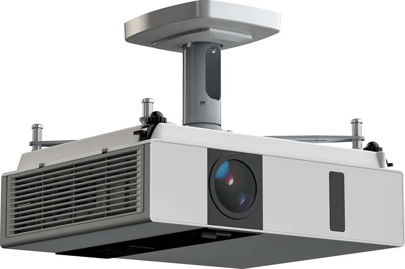
The Kindermann Comfort² 10 silber is a compact ceiling projector mount engineered for stable, low-profile installations. With a fixed 12 cm distance from projector to ceiling, this silver-finished bracket is ideal for small rooms, classrooms, meeting spaces, and home theaters where a neat, robust mounting solution is required. It supports standard projector mounting patterns from 75 to 370 mm and accepts three- or four-arm configurations to match different projector footprints.

Designed for easy installation by qualified personnel, the Comfort² 10 emphasizes safe attachment and clear cable management. The unit includes a ceiling column with a decorative rosette and closing plugs for screw covers. Unlike the taller Comfort² models, the Comfort² 10 does not feature the internal cable channel or telescopic height adjustment, making it a straightforward solution when a minimal drop is preferred.

Practical features include an adjustable projector holder with distance elements and multiple screw sets (M3/M4/M5/M6) and washers to fit a wide range of devices. A quick-exchange mounting interface simplifies removal and reattachment for maintenance. The mount allows ±180° rotation and approximately ±20° tilt through a 3D joint, enabling accurate image alignment and keystone correction when combined with projector settings.

Safety and reliability are core to the design: mounting should only be carried out on structurally sound ceilings such as hardwood, steel beams, or concrete, using suitable screws (not included). The holder supports projectors up to 20 kg, and fastening bolts must be threaded at least three turns into the projector’s thread inserts. Ventilation clearance around projector air outlets is emphasized to prevent overheating.

Installation guidance highlights testing projection alignment prior to final tightening, routing cables with care to avoid strain when rotating the projector, and checking all fastenings after assembly. The Comfort² 10 is a low-complexity, dependable choice where minimal ceiling drop and a tidy, silver aesthetic are desired.

Notes

  • Model Comfort² 10 provides a fixed 12 cm projector-to-ceiling distance.
  • Maximum projector weight: 20 kg. Mounting material and screws not included.
  • Not equipped with internal cable channel or telescopic adjustment (unlike larger Comfort² models).
  • Ensure ventilation grilles remain unobstructed and cables are routed to avoid stress when adjusting.
M: OA-GPT-5-NAN

© Copyright 2026 Manual.ly