
IVT Shunt Manual
PDF manual · 6 Pages
English



Quick check
Incorrect answer, please try again.
Chat with your IVT Shunt manual using AI
Get instant AI answers from your IVT Shunt manual
Ask anything about the IVT Shunt. Answers come from this manual, with the pages they are based on.
Ask a Question
Do you recommend Shunt?
Yes NoFrequently Asked Questions
The IVT controller auto-detects 12V or 24V systems. Two models are typical: 6A (6A charge/load) and 8A (8A charge/load). Nominal charge-end voltages are 13.7V/27.4V with higher gassing setpoints and temperature compensation.
Is this answer helpful?
It uses IU-style PWM shunt regulation: when the final charge voltage is reached the regulator rapidly reduces charging by pulse shunting, maintaining voltage without fully cutting current. An internal temperature sensor adjusts end voltages to prevent overgassing and battery stress.
Is this answer helpful?
Yes. The controlled gassing function must be disabled for sealed/gel batteries and many marine installations. Deactivation is done by opening the unit and removing the JP1 jumper as described in the manual.
Is this answer helpful?
Connect in order: battery first (use 2.5–4 mm² cable), solar panel second, loads last. Install a fuse on the battery positive unless using short-circuit-proof connections. Mount the unit near the battery in a dry, ventilated spot with terminals facing downward.
Is this answer helpful?
The regulator disconnects the load when battery voltage falls to the deep-discharge threshold (e.g., ~11.1V for 12V systems) and reconnects automatically when solar charging raises voltage above the reset threshold, preventing permanent battery damage.
Is this answer helpful?
No. The unit must be used in closed, dry areas; avoid humidity over 80%, temperatures above 50°C, dust, solvents or corrosive atmospheres. Batteries should be well ventilated to avoid explosive gases during charging.
Is this answer helpful?
No routine maintenance is required beyond visual checks. At end of life, don’t dispose with household waste; take the device to an electronics recycling collection point per local regulations to enable proper material recovery.
Is this answer helpful?
Advantages and Disadvantages
Advantages

- Automatic 12/24V detection simplifies use across different systems without manual switching.
- Temperature compensation adjusts charge and gassing thresholds to prolong battery life.
- IU (PWM shunt) charging reduces overgassing while maintaining effective charge current.
- Built-in deep-discharge protection prevents battery damage by disconnecting loads at low voltage.
- Compact, low-power design with clear LED status indicators and simple three-step wiring.
Disadvantages

- Shunt PWM method dissipates excess energy as heat, limiting efficiency for larger panels.
- Gas-control must be manually disabled for sealed (gel) batteries or marine use.
- Limited to small systems (6A or 8A), unsuitable for higher-current installations.
- Requires careful wiring order and a fuse on battery positive to avoid short-circuit hazards.
- Basic feature set lacks advanced telemetry, MPPT capability, or programmable profiles.
Product Specification
Note
Prices partly include 0% VAT tax rates for AT and DE
Type
Charge controller
Product Description
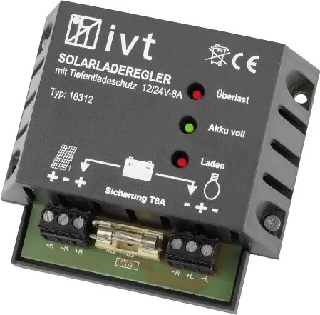
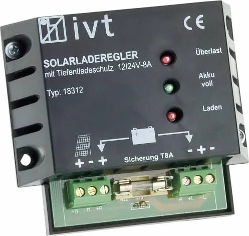
IVT Shunt Solar-Charge Controller IVT 12/24V Manual
The IVT Shunt Solar-Charge Controller IVT 12/24V is a compact, reliable solar charge regulator designed for small photovoltaic systems. It supports automatic 12/24V system recognition and provides key battery protections: overcharge control with IU (PWM shunt) charging, temperature-compensated charge thresholds, controlled gassing cycles, and deep-discharge cut-off. Models include 6A and 8A variants, both offering low standby consumption and built-in temperature sensing for adaptive charge regulation across -25°C to +50°C.
The controller’s shunt-based PWM method reduces charging current to avoid exceeding final charge voltages while maintaining a trickle charge. This conserves battery life and speeds up safe charging. An automatic gas-control pulse prevents acid stratification in flooded lead-acid batteries; this feature must be disabled when charging sealed gel batteries or using the unit aboard boats.
Installation is straightforward: connect battery first (use 2.5–4 mm² cable, fuse at battery + unless short-circuit-proof wiring is used), then the solar panel, then loads. The unit must be mounted near the battery, protected from weather, with terminals facing downward to ensure ventilation. LEDs indicate charging status, full battery, and overload. Built-in protections include reverse-polarity warnings, load disconnect on low voltage, and an overload indicator.
Technically, the 8A model supports up to 8A charge and load currents; the 6A model supports 6A. Typical charge-end voltages are 13.7V (12V mode) / 27.4V (24V mode) with gas-stage and temperature-adjusted setpoints reaching 14.1V / 28.2V and gassing-targets near 14.5V / 29V. Deep-discharge cut-offs and automatic reconnect thresholds protect battery health and restart loads when solar recharge is sufficient.
Whether used for off-grid lighting, small cabin systems, or auxiliary battery maintenance, this IVT regulator is aimed at users who need a simple, robust charge controller with essential automatic controls and clear installation guidance.
Notes
- Disable gas-control when charging sealed lead-acid (gel) batteries or when installed on boats. Follow the manual to remove jumper JP1 to deactivate gas-control.
- Always fuse the battery positive connection unless using certified short-circuit-proof cabling.
- Install in dry, well-ventilated spaces and avoid environments above 50°C or >80% humidity.
Search for 67,706 Manuals online


Type-in Brand or Model