
IVT Shunt 20A Manual
PDF manual · 8 Pages
English



Quick check
Incorrect answer, please try again.
Chat with your IVT Shunt 20A manual using AI
Get instant AI answers from your IVT Shunt 20A manual
Ask anything about the IVT Shunt 20A. Answers come from this manual, with the pages they are based on.
Ask a Question
Do you recommend Shunt 20A?
Yes NoFrequently Asked Questions
No, the regulator automatically detects and operates in both 12 V or 24 V configurations without requiring manual switching from the user.
Is this answer helpful?
It adjusts the charging voltage and gas regulation based on ambient temperature to prevent damage and ensure proper battery chemistry management.
Is this answer helpful?
A green light indicates charging is in progress during the day, while a red light signals load disconnection due to deep discharge or low voltage.
Is this answer helpful?
Yes, but you must disable the gas regulation function before installation to prevent explosion risks associated with fuel on vessels.
Is this answer helpful?
The load disconnects automatically to protect the battery cells from permanent damage caused by excessive discharge levels.
Is this answer helpful?
The unit has a built-in 20 A fuse, but additional fuses are recommended for individual consumer connections to ensure circuit safety.
Is this answer helpful?
The sensor cable should be approximately 1.5 meters long and attached directly to the battery housing for accurate temperature readings.
Is this answer helpful?
Advantages and Disadvantages
Advantages

- Automatic 12/24 V switching without manual intervention.
- Temperature compensation adjusts charging voltage for battery longevity.
- IU charging method protects against overcharging and gas formation.
- Deep discharge protection prevents battery cell degradation.
- Compact design with minimal power consumption.
Disadvantages

- Gas regulation must be disabled for use on boats.
- Requires careful polarity checking to avoid component damage.
- Terminals must face downward for proper protection.
- Sensor must be attached near the battery for accuracy.
- Cannot be used in areas with humidity over 80 percent.
Product Specification
Note
Prices include 0% VAT rates for Austria and Germany in some cases.
Type
Charge Controller
Product Description
Comprehensive Guide for Your Solar Setup
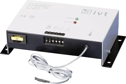
When planning a photovoltaic installation, safety and efficiency are top priorities. The IVT Shunt Solar Charge Regulator 12/24V, 20A Manual offers a guide for users managing lead battery storage. This device is recognized for reliability and compact design. It serves as a central component ensuring your energy system remains stable.
Automatic Voltage Adaptation
One of the most impressive features is the automatic switching capability. The system operates seamlessly in both 12 V and 24 V configurations. Users do not need to perform any manual switches. The regulator detects the system voltage and adjusts its operation accordingly. This flexibility makes it suitable for various residential or mobile setups without extra hardware costs. The unit adapts quickly, making transition between voltage levels entirely invisible to the user during normal operation.
Battery Protection Mechanisms
Lead batteries require careful monitoring to prevent damage. The unit includes deep discharge protection to avoid cell degradation. When voltage levels drop below a safe threshold, the load disconnects automatically. It reconnects only when sufficient power returns from the solar cells. Overcharge protection is equally critical. Excessive charging causes gas production which harms the battery. The regulator uses an IU charging method to maintain optimal levels without shutting off completely. This controlled charging reduces stress on the battery.
Temperature Management
Performance varies with environmental conditions. An integrated temperature sensor compensates for changes. The sensor connects via a 1.5-meter cable and should attach near the battery. This ensures charging voltages adjust correctly for heat or cold. Proper compensation prevents acid formation and maintains battery health.
Safety and Installation
Installing the device requires strict adherence to safety guidelines. Connections must follow the correct polarity to prevent damage. Fuse protection is mandatory on the positive battery terminal to avoid short circuits. The unit must be mounted in a dry, closed space to avoid humidity issues. Terminals should face downward to ensure proper ventilation and protection against condensation. Gas control must be disabled if the system is located on a boat to prevent explosion risks.
LED Indicators and Troubleshooting
The device features two LEDs to indicate status. A green light shows charging in progress during the day. A red light warns of deep discharge or load disconnection. If both lights remain off, check the battery polarity or fuses. Troubleshooting involves checking connections and ensuring no solar panels are reversed.
Technical Specifications Overview
Understanding the technical limits is essential for compatibility. The nominal voltage handles 12 or 24 volts automatically. The maximum load current is 20 amps. The self-consumption is minimal at 4 mA. Dimensions are compact, measuring 175 by 100 by 45 millimeters. The operating temperature range spans from minus 25 degrees to plus 50 degrees Celsius. Knowing these limits prevents operation outside safe parameters.
Conclusion
Users should consult the IVT Shunt Solar Charge Regulator 12/24V, 20A Manual before energizing the system. Proper usage leads to a longer lifespan for all connected components. Always refer to these instructions for safety and optimal efficiency in your energy system.
Search for 67,706 Manuals online


Type-in Brand or Model