
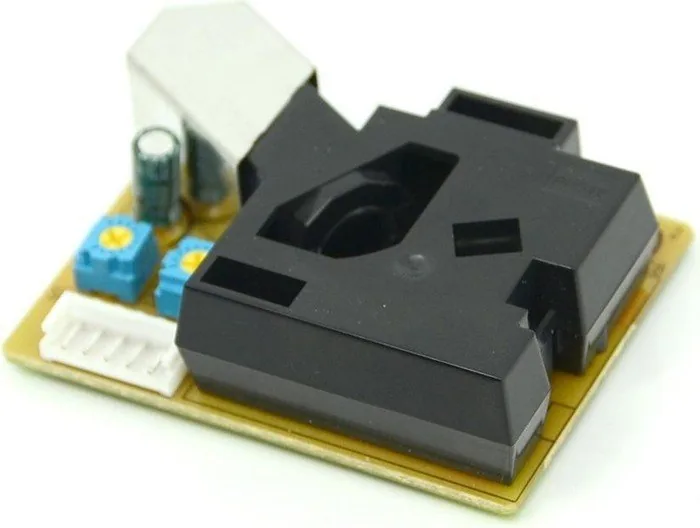
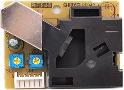
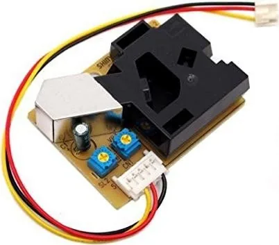
Grove Dust Sensor Manual
PDF manual · 4 Pages
English



Quick check
Incorrect answer, please try again.
Chat with your Grove Dust Sensor manual using AI
Get instant AI answers from your Grove Dust Sensor manual
Ask anything about the Grove Dust Sensor. Answers come from this manual, with the pages they are based on.
Ask a Question
Do you recommend Dust Sensor?
Yes NoFrequently Asked Questions
It detects light scattered by particles passing through an infrared beam and outputs analog and two thresholded digital signals. It indicates relative particle presence and responds differently to particle sizes, but is not a precise mass monitor without calibration.
Is this answer helpful?
Two comparator thresholds produce pulses when the amplified signal exceeds set voltages. One output corresponds roughly to smaller particles (~1 µm) and the other to larger particles (~2.5 µm), providing coarse size-sensitive detection after calibration.
Is this answer helpful?
The sensor runs from 5V with the LED drawing ~33 mA and the heater ~50 mA. Use a well-filtered supply because voltage fluctuations change LED output and mimic particle signals. Ensure your power source can supply the heater current.
Is this answer helpful?
No. The device produces pulses from aggregate scattering events shaped by electronics and airflow. It behaves as a hybrid between a counter and photometer; true single-particle counting is not guaranteed without specific configuration and validation.
Is this answer helpful?
Calibrate by co-locating with reference instruments, adjust gain and threshold trimmers, and consider tapping the raw analog signal for custom processing. Testing with known aerosols helps determine sensor response characteristics.
Is this answer helpful?
Yes. Users often experiment by measuring heater temperature, replacing the thermal plume with a small fan or blower, or sampling differently to study effects on pulse frequency and amplitude. Such modifications require re-validation.
Is this answer helpful?
Commonly a JST EH series connector: EHR-5 housing with SEH-001T crimp terminals. These parts are widely available from major distributors.
Is this answer helpful?
Advantages and Disadvantages
Advantages

- Simple, low-cost optical design suitable for makers and prototypes
- Onboard analog conditioning with adjustable gain and thresholds
- Thermal plume sampling improves particle entrainment consistency
- Two comparator outputs give coarse size-sensitivity bands
- Standard parts and connectors make repairs and hacks easy
Disadvantages

- Not a true single-particle counter—response is averaged and aerosol-dependent
- Requires stable, well-filtered 5V supply to avoid signal artifacts
- Calibration needed to relate outputs to actual mass or count concentrations
- Heater increases power consumption and may complicate deployments
- Optical scattering varies by particle type, limiting direct quantitative accuracy
Product Specification
Manufacturer
SeeedStudio
Type
Dust sensor (PPD42NS)
Platform
Grove, C-Control Open Duino
Connection
Grove port
Power supply
via Host
Product Description
Grove Dust Sensor Manual — Overview and Practical Guide
The Grove Dust Sensor is an affordable optical particulate detector designed for hobbyists and prototypers. It uses an infrared LED and a photodiode in a baffled optical chamber to measure light scattering from airborne particles. A small heater creates a thermal plume to entrain particles through the detection zone, improving sampling consistency. Onboard analog amplification and comparator stages convert the photodiode signal into conditioned outputs usable by microcontrollers and data loggers.
How it works
Particles convect through the infrared beam where scattered light at ~45° is focused onto a photodiode. The photodiode is reverse biased and its current variations are integrated and shaped by passive components before being amplified by a multi-section op-amp. Filter networks emphasize pulses of certain durations, while comparator stages generate digital pulse outputs at two thresholds corresponding roughly to smaller and larger particle ranges.
Key components and signal path
The optical chamber, LED and photodiode form the sensing core. A heater (approx. 100 Ω) produces a thermal updraft to entrain particles. The photodiode current is slowed by a small capacitor, then amplified through staged op-amp sections with adjustable gain trimmers. Frequency shaping (high-pass and low-pass) makes the device most responsive to pulses near a few hertz. Two comparator thresholds produce two digital outputs calibrated to represent different particle-size sensitivities.
Usage notes and calibration
Power stability matters: LED light output and thus sensitivity depend on a well-filtered 5V supply. Sensitivity and gain trimmers allow calibration to standards or field references; manufacturer calibration likely accounts for LED and detector variability. Expect the sensor to behave as a hybrid—neither a strict single-particle counter nor a volumetric photometer—so interpret readings accordingly and, when possible, co-locate with reference instruments for calibration and validation.
Practical modifications and experiments
You can tap the raw analog signal for custom processing, measure heater temperature or convective airflow, or alter the sampling method (for example replace the heater-driven plume with a small fan or blower) to explore response differences. Frequency and pulse analysis at op-amp stages helps relate electronics to particle residence time in the beam.
Notes
- The device draws most power from the heater (~50 mA) and the LED (~33 mA); ensure adequate supply capacity and filtering.
- Connector type commonly used is JST EH series (EHR-5 housing with SEH-001T crimp terminals).
- Optical scattering response varies by particle type; readings are aerosol-dependent and need experimental validation.
Search for 67,706 Manuals online


Type-in Brand or Model